Configuration
R&S
®
TS7124M
98User Manual 1525.5394.02 ─ 05
1 = Rear chamber wall
2 = Two spacers (do NOT remove)
3 = Two rear long-distance bolts (remove)
4 = Two disk fixtures (do NOT remove)
5 = Front chamber wall
6 = Two spacers (do NOT remove)
7 = Two front short-distance bolts (remove)
5.
NOTICE! If the DUT holder collides with the antenna ring, damage can result.
Before lifting the full antenna ring out of the RF shielded box, make sure that the
DUT holder is not within the chamber at the same time. Either manually pull the
drawer open (while preventing the chamber from tilting) or make sure that the DUT
holder is not attached to the drawer's door.
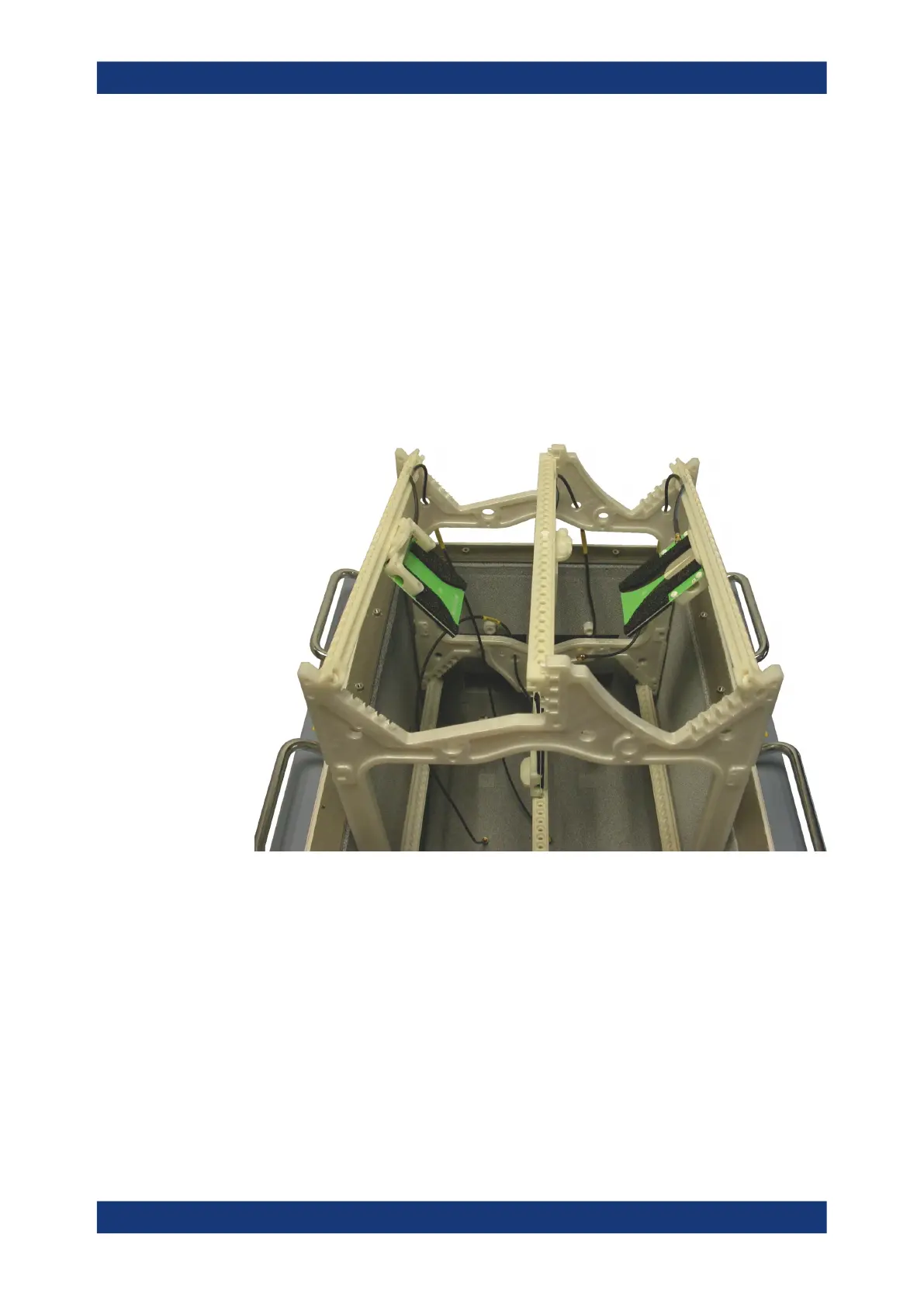
6. Carefully and slowly lift the full antenna ring out of the RF shielded box.
Figure 7-31: Take the full antenna ring out of the chamber
7. Place the full antenna ring outside the chamber
Installing an antenna ring or holder
 Loading...