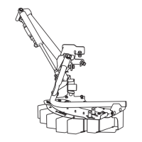
Fig. 26: Order of connecting the machine lines to the tractor
[1] Ball
coupling (a variant with a pin coupling is
also available)
[2] Hopper cover hydraulic line
[3] Hopper cover hydraulic line
[4] Control block hydraulic line
[5] Pneumatic control line (pneumatic brake)
[6] Pneumatic line of the compressed air tank
(pneumatic brake)
[7] Return hydraulic line
[8] ISOBUS connector
[9] Lighting connector
Fig. 27: Connection lines
[1] Pressure line
[2]
Free return
[3] Load sensing signal line
[4] ISOBUS connector plug
[5] Lighting cable
6. Commissioning
54
5903494 AERO GT 60.1
 Loading...