EasyManuals Logo

Raven ISOBUS Product Control User Manual

Default Icon
86 pages
To Next Page IconTo Next Page
To Previous Page IconTo Previous Page
Page #19 background imageLoading...
Page #19 background image
CHAPTER
3
Manual No. 016-0171-362 Rev. F 9
CHAPTER 3
INSTALLATION
MOUNT THE FLOW METER
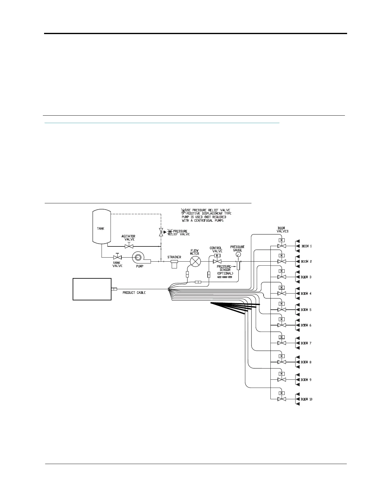
1. Mount the flow meter in the area of the boom valves as shown in Figure 1. All flow through the flow meter must
go to the booms, (i.e. no return line to tank or pump after flow meter).
2. Mount the flow meter horizontal to the ground.
3. For best results, allow a minimum of 7-1/2” [20 cm] of straight hose on inlet of flow meter. Bend radius of hose
on outlet of flow meter should be gradual.
4. Flow must be in direction of arrow on flow meter.
FIGURE 1. Flow Control System
To ISObus
Control Harness
To sections 6 through 16

Table of Contents

Questions and Answers:

Question and Answer IconNeed help?

Do you have a question about the Raven ISOBUS Product Control and is the answer not in the manual?

Raven ISOBUS Product Control Specifications

General IconGeneral
BrandRaven
ModelISOBUS Product Control
CategoryControl Unit
LanguageEnglish

Related product manuals