CHAPTER 4
14 ISOBUS Product Control Installation & Operation Manual
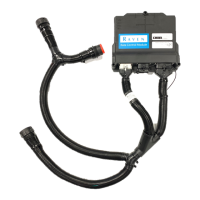
3. Select the tools icon at the right side of the screen to display the calibration screen.
NOTE: For a description of the information displayed on the product control home screen, see the Product
Control Home Screen section on page 37.
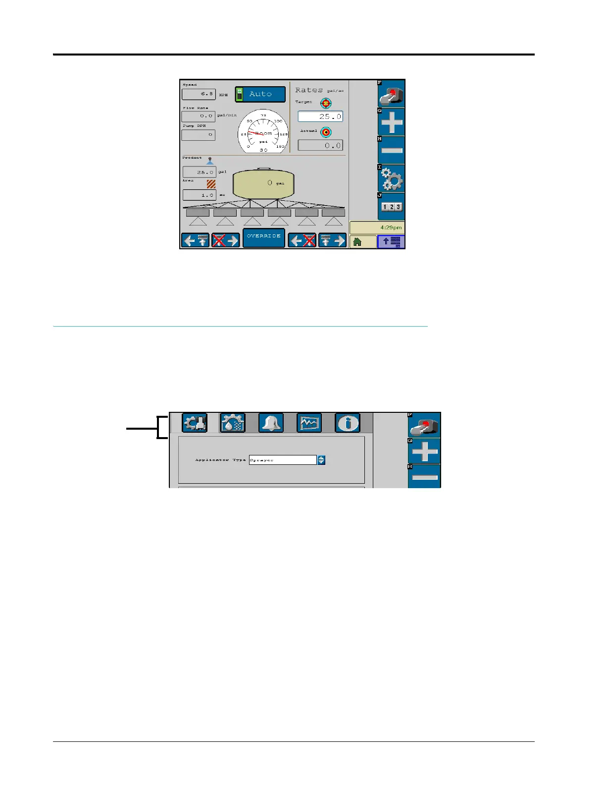
CALIBRATION SCREEN
The various settings and calibration values are displayed in three categories which can be viewed by selecting the
icons at the top of the screen.
• Implement Calibration - Access the vehicle or implement settings to adjust the total width, number of sections,
and the section width.
• Product Control Settings - Access the product control settings to adjust settings such as the meter or valve cals
or adjust the rate +/- or product control home screen display.
• Alarms Setup - Access the alarms setup screen to modify the conditions of which the machine operator should
be aware during product control applications.
• Information - Select the information icon to view the ISOBUS product control node hardware and software
version numbers.
Calibration
Categories
Implement
Product
Control
Alarm
Setup
Information
Diagnostics
 Loading...