4
Manual No. 016-0171-362 Rev. F 25
ISOBUS PRODUCT CONTROL NODE CALIBRATION
To properly set the pressure cal:
1. Charge the AccuFlow HP system (review the AccuFlow, AccuFlow HP, and AccuFlow HP Plus Installation and
Operation Manual and follow all safety instructions and warnings when charging the AccuFlow HP system).
2. Allow the pressure to stabilize and, with the control valve and any section valves in the closed position, read the
gauge pressure on the gauge assembly.
3. For an AccuFlow HP system, navigate to the Pressure Control Setup screen (refer to the instructions provided
under the HP Pressure or HP Plus Control Setup section on page 23) and enter the gauge reading.
4. For an AccuFlow HP Plus system, enter the pressure cal value for the outlet pressure transducer as “Pressure
Cal” on the product control calibration screen. Enter the pressure cal value for the inlet pressure transducer as
“Pressure Cal 2” on the product control calibration screen.
NOTE: Do not enter the rate cal or target pressure as the pressure cal value. The pressure cal value must only
be used to calibrate the pressure transducer connected to the Raven ISOBUS product control system.
Refer to Target Pressure (NH3 Applications) section on page 40 to set the target pressure for the
AccuFlow HP boost pump.
ACTUAL PRESSURE DISPLAY
Once the AccuFlow pressure transducer is properly calibrated, the current pressure of the anhydrous ammonia
product is displayed at the bottom of the HP Pressure Control Setup screen.
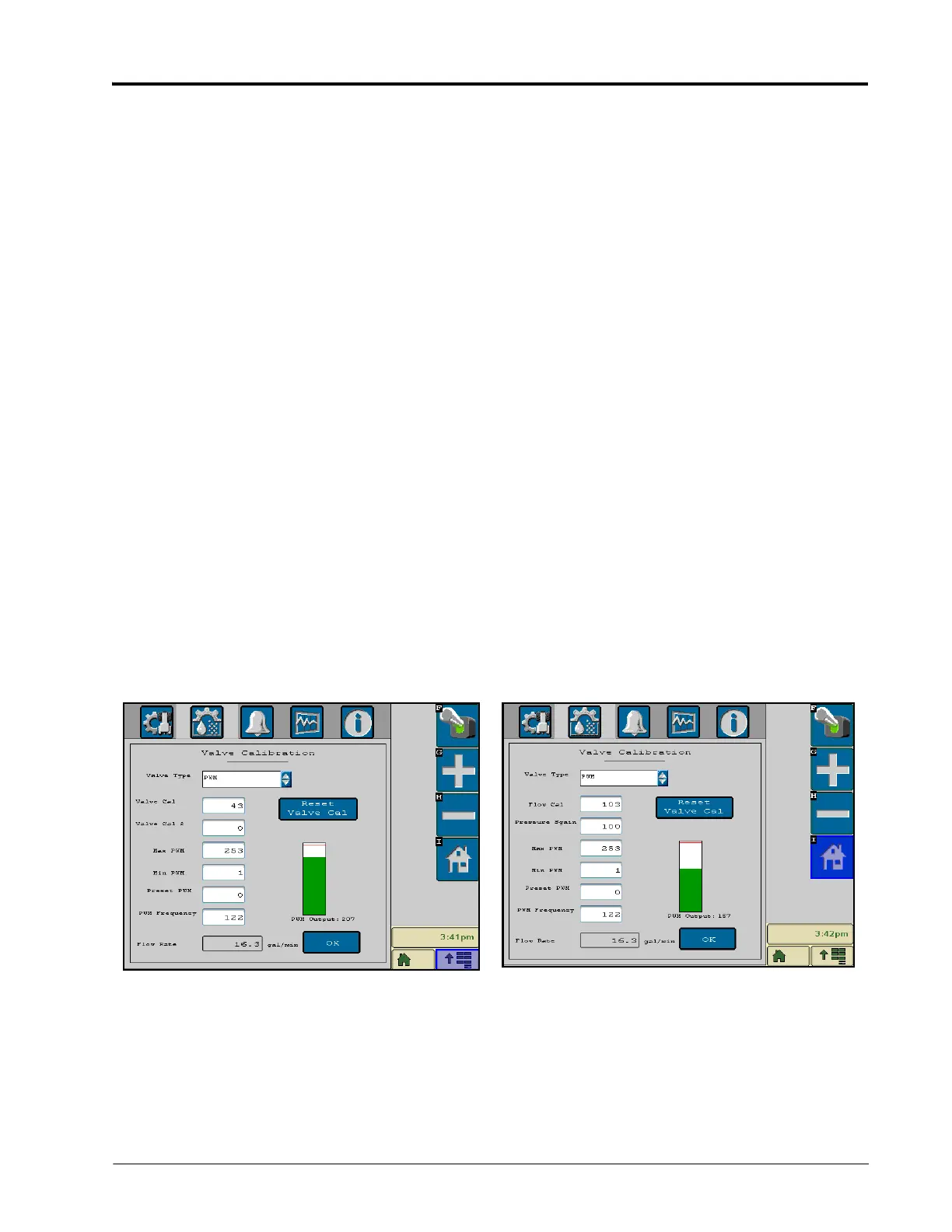
PWM OUTPUT DISPLAY
The PWM output display represents the currently programmed min and max PWM values as well as the current
PWM output of the valve.
PULSE WIDTH MODULATION VALVE SETUP
If a pulse width modulation (PWM) type valve is selected as the valve type on either the Valve Calibration or
Spinner/Fan Control Setup screens, the following additional settings will be displayed.
 Loading...