3
Manual No. 016-0171-362 Rev. F 11
INSTALLATION
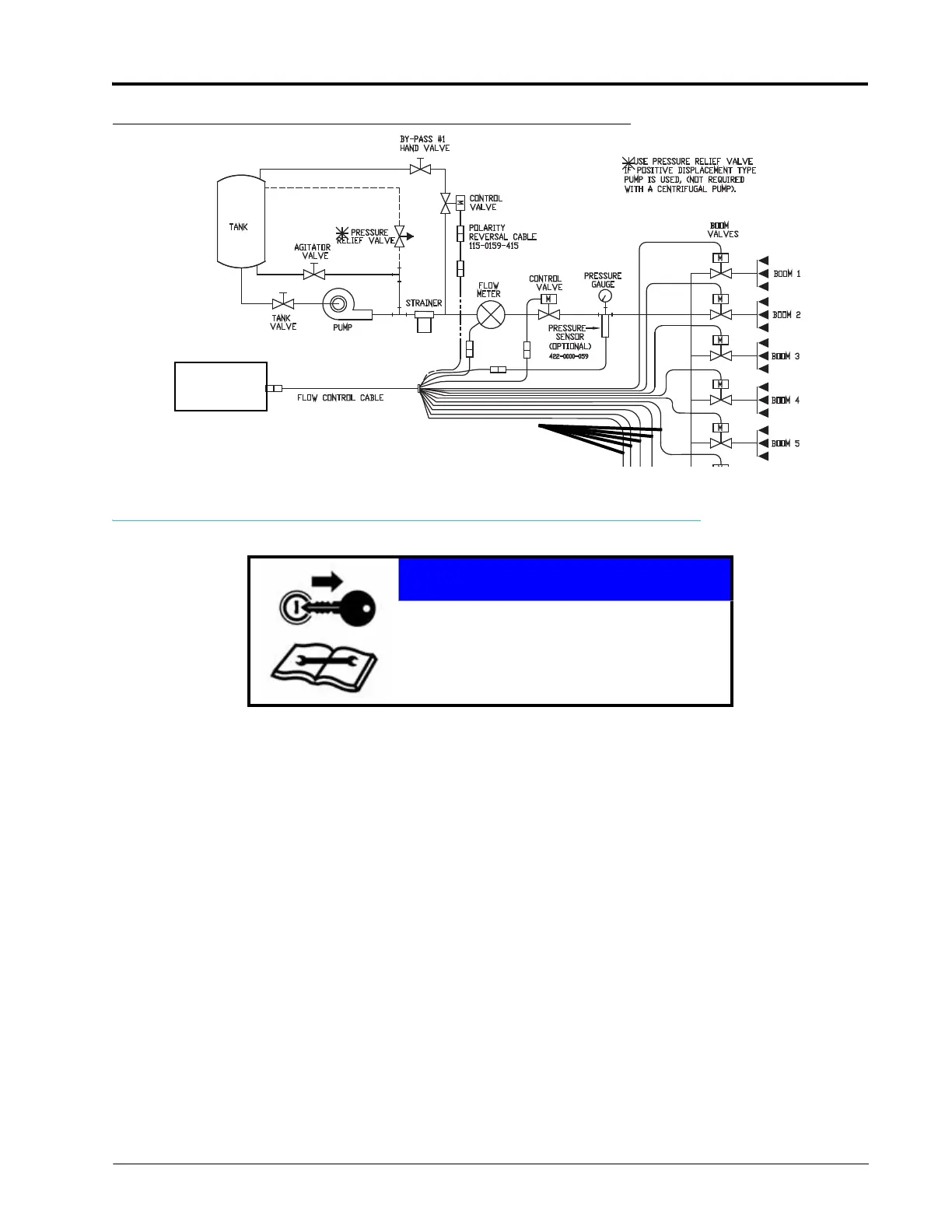
FIGURE 2. By-Pass Plumbing Diagram
MOUNT THE NODE
The Raven ISOBUS node is mounted to the specific implement with which the product control features are to be
used.
When selecting a location to mount the node, consider the following points:
• The node mounting location must not create tripping hazards and allow cable routing to avoid crimping or
damaging the cables or the node connections.
• The node should not be directly exposed to moisture or chemicals during normal operation and should be
mounted so that the node connectors face down (toward the ground).
• For wiring connections made outside the cab or protected enclosure, apply dielectric silicone grease to the pins
(P/N 222-0000-006) on the male end of the connectors. Application of the grease will help prevent corrosion
to the pins and wires.
• Mount the node to a flat surface in a location where it will not be jarred during normal equipment operation.
INSTALLATION BEST PRACTICES
The information below illustrates proper methods for wiring a CANBUS system. The diagrams provided later in this
chapter are a good reference for both OEM and aftermarket installations. The main points are summarized below.
1. Always use sealed connectors with dielectric grease. Unsealed, crimped connections (i.e. butt connectors)
should be avoided.
NOTICE
Be sure to read all safety instructions and follow
all installation procedures to ensure proper
installation of the ISOBUS system.
To ISObus
Control Harness
 Loading...