APPENDIX 8
62 ISOBUS Product Control Installation & Operation Manual
VALVE CAL
To ensure that the proper amount of product is being applied, the valve cal must be programmed for the type of
control valves connected to the ISOBUS product control system. The ISOBUS uses the valve calibration number to
adjust the response time of the control valve motor to changes in the vehicle speed.
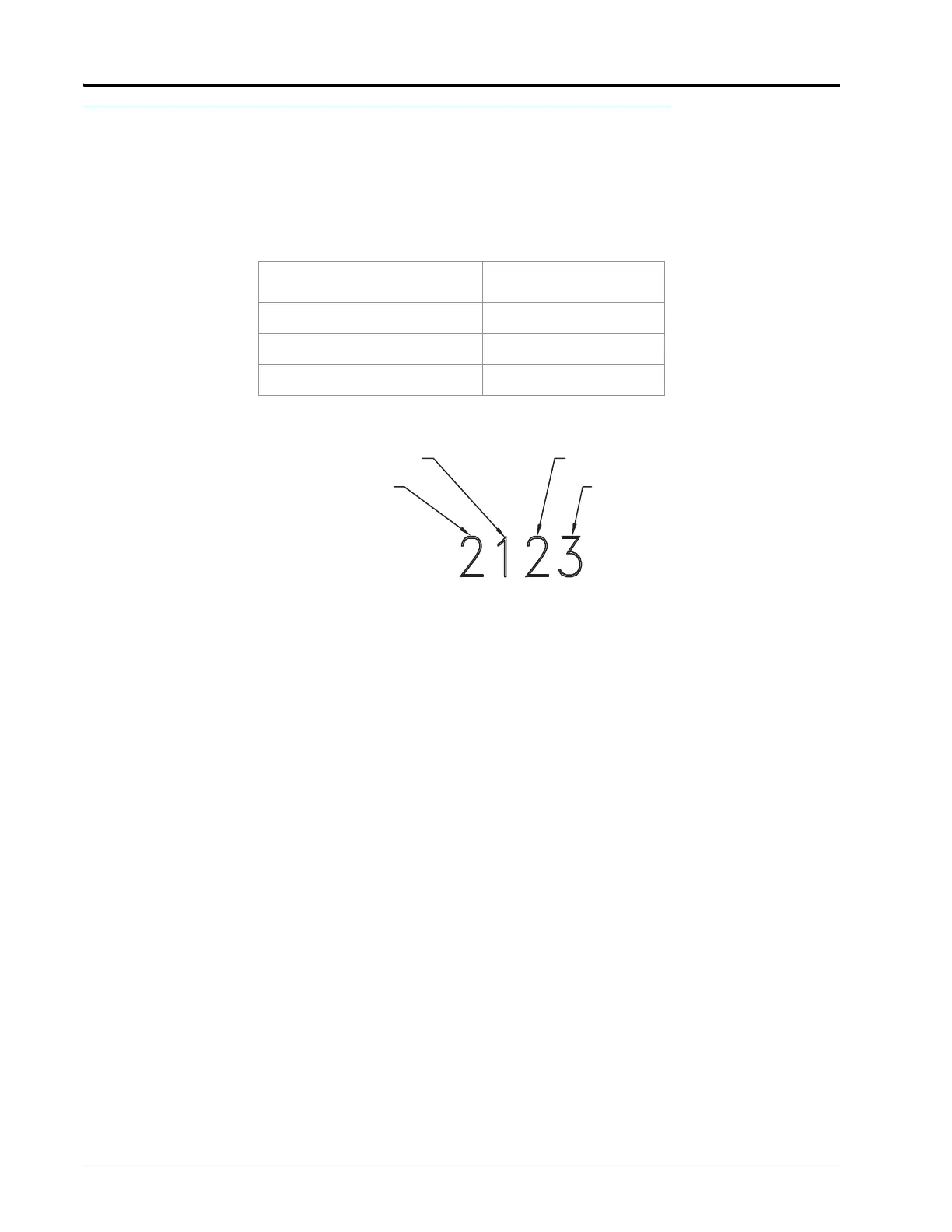
The following control valve calibration numbers are recommended for the valves listed:
Each digit in the calibration number corresponds to a specific function of the valve. The following functions apply
to the digits in the valve calibration number:
VALVE BACKLASH DIGIT
This value controls the time of the first correction pulse after detecting a change in correction direction. The values
range from 1 to 9, where 1 is for a short pulse and 9 is for a long pulse.
VALVE SPEED DIGIT
This value controls the response time of the control valve motor. If the valve speed setting is too fast, the valve will
over correct and the system can start to oscillate. The following valves have specific values:
• Standard Control Valve: This valve has a range of values from 1 to 9, with 1 being slow and 9 being fast.
• Fast and Fast Close Control Valve: These valves have a range of values from 0 to 9, with 0 for fast and 9 for slow.
BRAKE POINT DIGIT
The brake point digit sets the percent away from the target rate at which the control valve starts to turn at a slower
rate so that it does not overshoot the target rate. The values range from 0 to 9, where 0 is a 5% rate, 1 is a 10% rate,
and 90 is a 90% rate.
DEAD BAND DIGIT
The dead band digit is the allowable difference between the target rate and the actual application rate. The values
range from 1 to 9, where 1 equals 1% difference and 9 equals 9% of the difference.
Valve Name Calibration Number
Standard Valve 2123
Fast or Fast Close Valve 743
PWM or PWM Close Valve 43
Dead Band
Break Point
Valve Backlash
Valve Speed
 Loading...