CHAPTER 3
12 ISOBUS Product Control Installation & Operation Manual
2. Isolate the power and ground sources for the console and node logic, or node processor, power on separate
leads to the vehicle battery or another source of clean power.
3. Use dedicated bus bars to connect the console and all nodes to the same source for both power and ground.
4. Provide relays to switch power on and off to avoid draining the battery. Raven recommends connecting CAN
nodes to a clean source of controlled power.
Following these recommendations will result in the most robust system possible while greatly reducing CAN
communication problems.
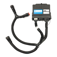
INSTALL ISOBUS PRODUCT CONTROL CABLING
1. Connect the large, rectangular connectors of the ISO product controller cable to the ISO product node.
2. Connect the round, female connector of the product controller cable to the product flow control cabling on the
implement.
3. Connect the round, male connector of the product controller cable to the ISOBUS hitch cable (ordered
separately).
NOTE: A ISO implement extension tee cable is necessary to connect the VT terminal with additional
hardware for Raven ISO features. Contact a local Raven dealer for more information.
4. Connect the active terminator adapter cable to the remaining round connector on the ISOBUS hitch cable and
install the Powell terminator (P/N 063-0172-964).
5. Connect the round, metal connector to the IBBC harness on the tractor. Refer to Appendix 7, System Diagrams.
MOUNT THE FOOT SWITCH
1. Mount the ISO node foot switch (P/N 063-0173-080) within the cab or drivers compartment of the vehicle
within easy reach of the operator.
2. Connect the foot switch extension cable (P/N 115-0171-865) to the foot switch and route to the vehicle hitch.
3. Connect the 4-pin deutsch connector on the foot switch extension cable to the ISOBUS hitch cable on the
implement.
IMPLEMENT PROXIMITY SWITCH
NOTE: Refer to the proximity switch installation sheet for instructions on mounting the proximity switch.
1. Locate the connector labeled ‘Prox. Switch’ on the CAN AccuFlow HP or “AccuFlow HP Plus” cable.
2. Connect the cable from the implement proximity switch body to the ‘Prox. Switch’ connector.
 Loading...