4
Manual No. 016-0171-362 Rev. F 17
ISOBUS PRODUCT CONTROL NODE CALIBRATION
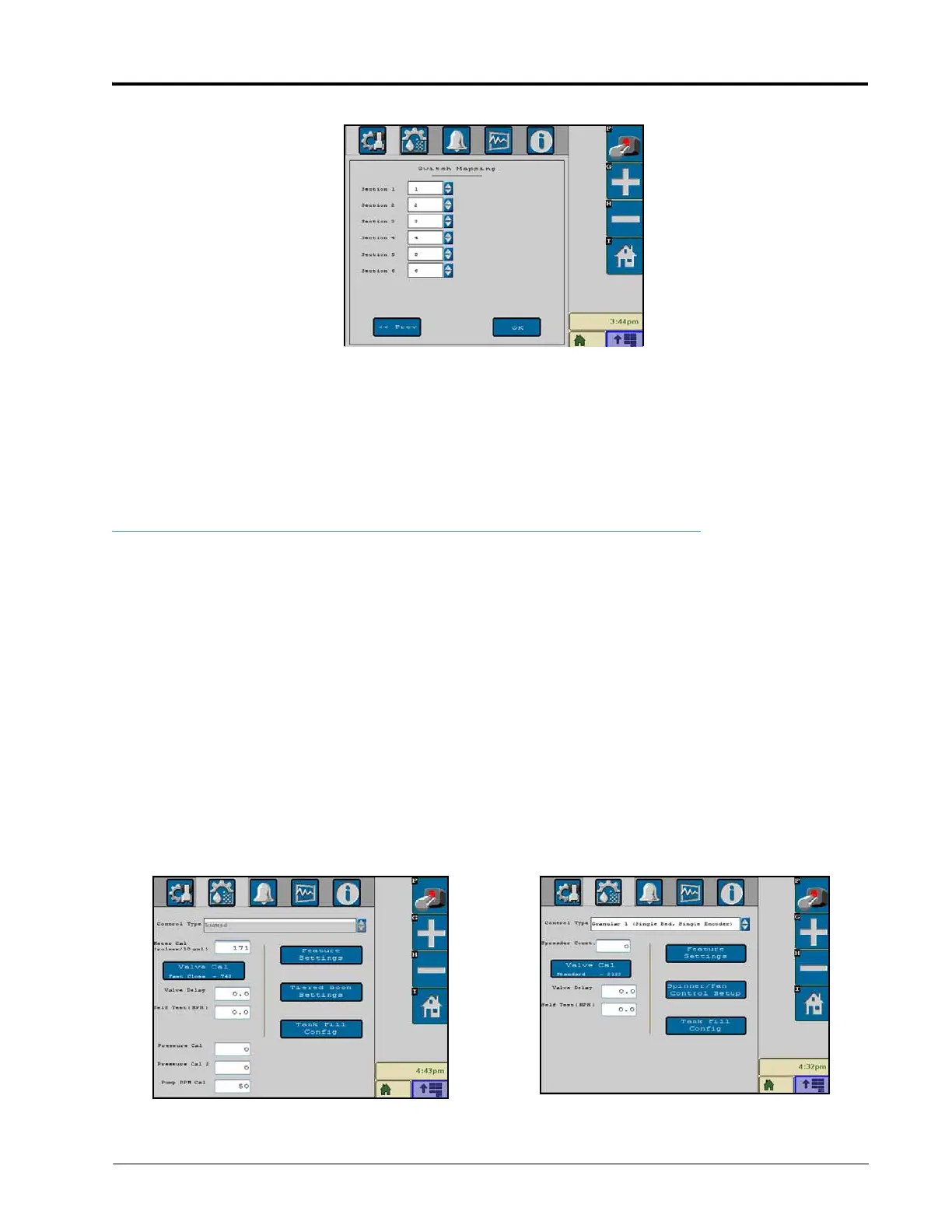
SWITCH MAPPING
NOTE: Switch mapping is only available if an optional Raven ISO Switch Box is detected on the ISOBUS.
The next screen in the section setup allows for a customized section to switch mapping setup. This allows the
operator to quickly control multiple sections using a single switch. This feature also allows the operator to control
an implement that has more sections than switches available on the switch box. To assign a switch to a section,
select the number of the switch in the menu for a section. Repeat the process for each remaining section.
PRODUCT CONTROL CALIBRATION TAB
The following settings may be viewed or modified when the implement category is selected:
• Control Type
• Meter Cal or Spreader Constant
• Valve Cal
• Valve Delay
• Tank Capac ity
• Pressure Cal (Liquid)
• Spinner/Fan Control Setup or HP (AccuFlow HP) Pressure Control Setup or HP+ Control Setup
• Self Test Speed
• Pump RPM Cal
• Feature Settings
• Tiered Boom Settings
The following product control home screen features and settings may be adjusted on the Feature Settings screen:
 Loading...