Electrical Components
D037/D038/D040/D041 4-128 SM
2. Controller box cover ( Section: Controller Box Cover)
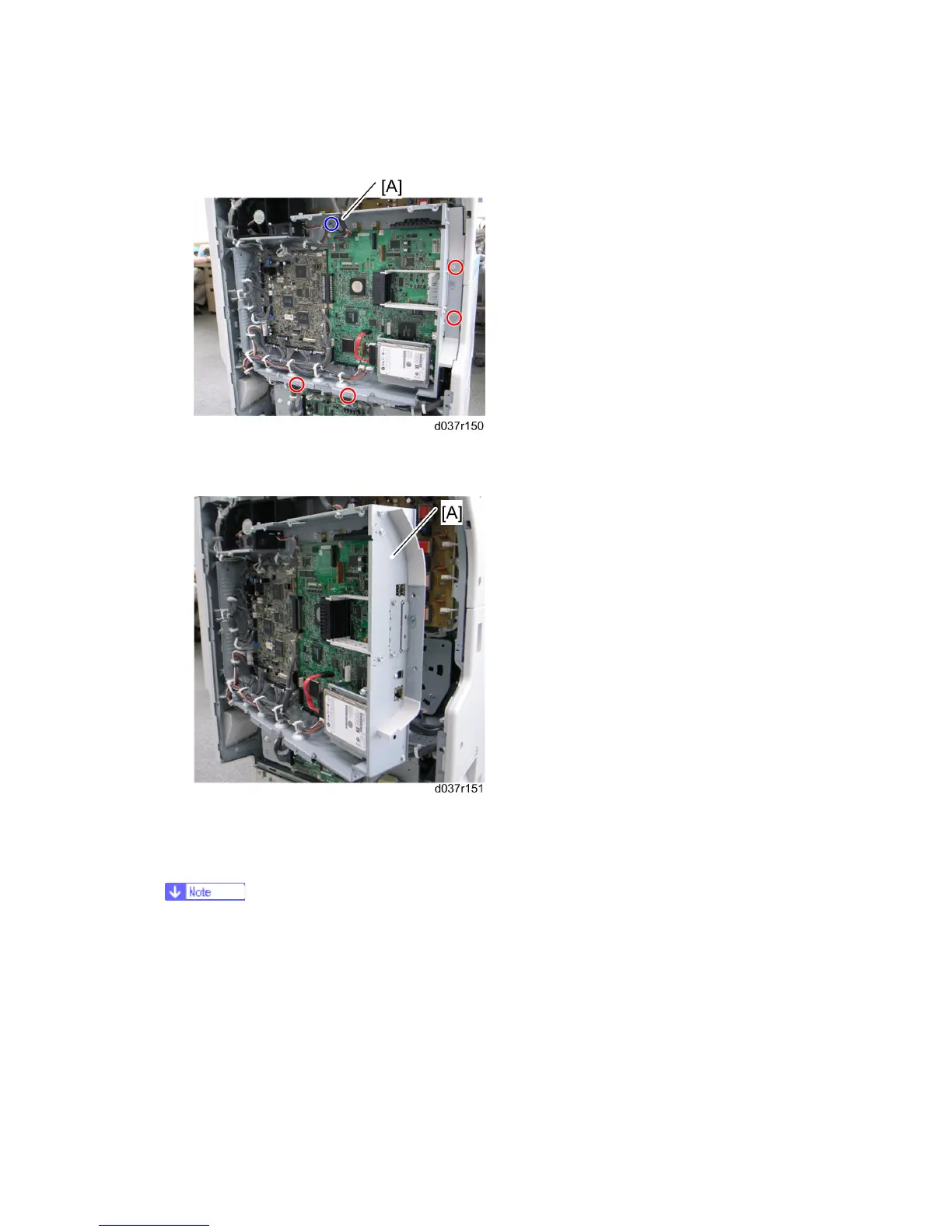
3. Remove the four screws and disconnect the scanner cable [A] ( x 1, ground screw x
1)
4. Open the controller box [A].
4.15.4 BCU
Do not replace the BCU and CTL boards together. If required, See NOTE 1 after
NVRAM Replacement section ( 4.15.12).
1. Rear cover ( Section: Rear Cover)
2. Controller box cover ( Section: Controller Box Cover)
⇒
Rev. 02/2009
 Loading...