Electrical Components
D426 2 SM
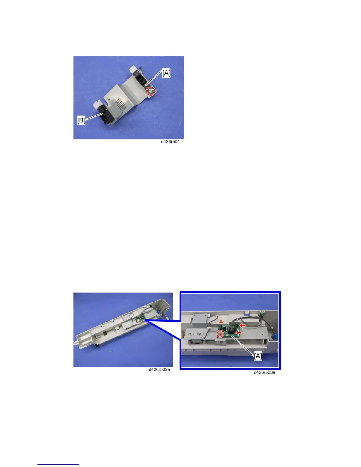
4. Sensors;
[A]: Paper sensor ( x 1)
[B]: 1-bin tray exit sensor (hooks)
When reinstalling these sensors
Both sensors have a 3-pin connector. Be careful to connect the correct harnesses from the
1-bin tray control board to each sensor.
The blue connector from the 1-bin tray control board must be connected to the paper
sensor.
The white connector from the 1-bin tray control board must be connected to the 1-bin
tray exit sensor.
1.1.2 1-BIN TRAY CONTROL BOARD
1. 1-bin tray unit
2. 1-bin tray bottom cover ( 1-Bin Tray Exit Sensor and Paper Sensor)
3. 1-bin tray control board [A] ( x 1, x 3)
 Loading...