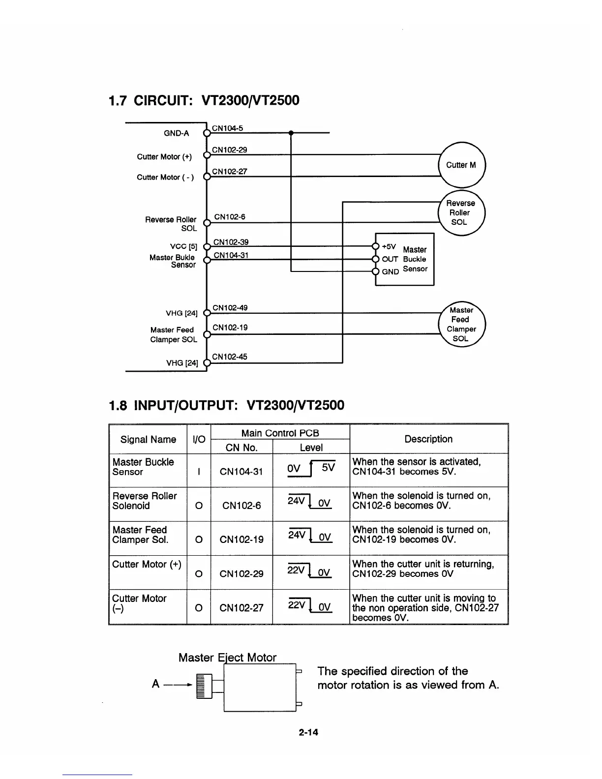
1.7 CIRCUIT: VT2300/VT2500
GND-A
Cutter Motor (+)
Cutter Motor ( - )
Reverse Roller
SOL
Vcc [5]
Master Bukle
Sensor
VHG [24]
Master Feed
Clamper SOL
VHG [24]
CN104-5
.
( )
CN1 02-29
( )
CN1 02-27
( )
CN1 02-49
CN102-19
1.8 lNPUT/OUTPUT: VT2300/VT2500
Signal Name
1/0
Main Control PCB
Description
CN
No.
Level
Master Buckle
Ov ff=
When the sensor is activated,
Sensor
I CNI04-31
CNI 04-31 becomes 5V.
Reverse Roller
2TI Ov
When the solenoid is turned on,
Solenoid
o CN1 02-6
CNI 02-6 becomes OV.
Master Feed
27J OV
When the solenoid is turned on,
Clamper Sol. o
CN102-19 CN1 02-19 becomes OV.
Cutter Motor (+)
%1 Ov
When the cutter unit is returning,
o CN102-29
CN1 02-29 becomes OV
Cutter Motor
When the cutter unit is moving to
(-)
o
CN1 02-27
Ziq Ov
the non operation side, CN1 02-27
becomes OV.
x
The specified direction of the
motor rotation is
as viewed from A.
2-14


 To Next Page