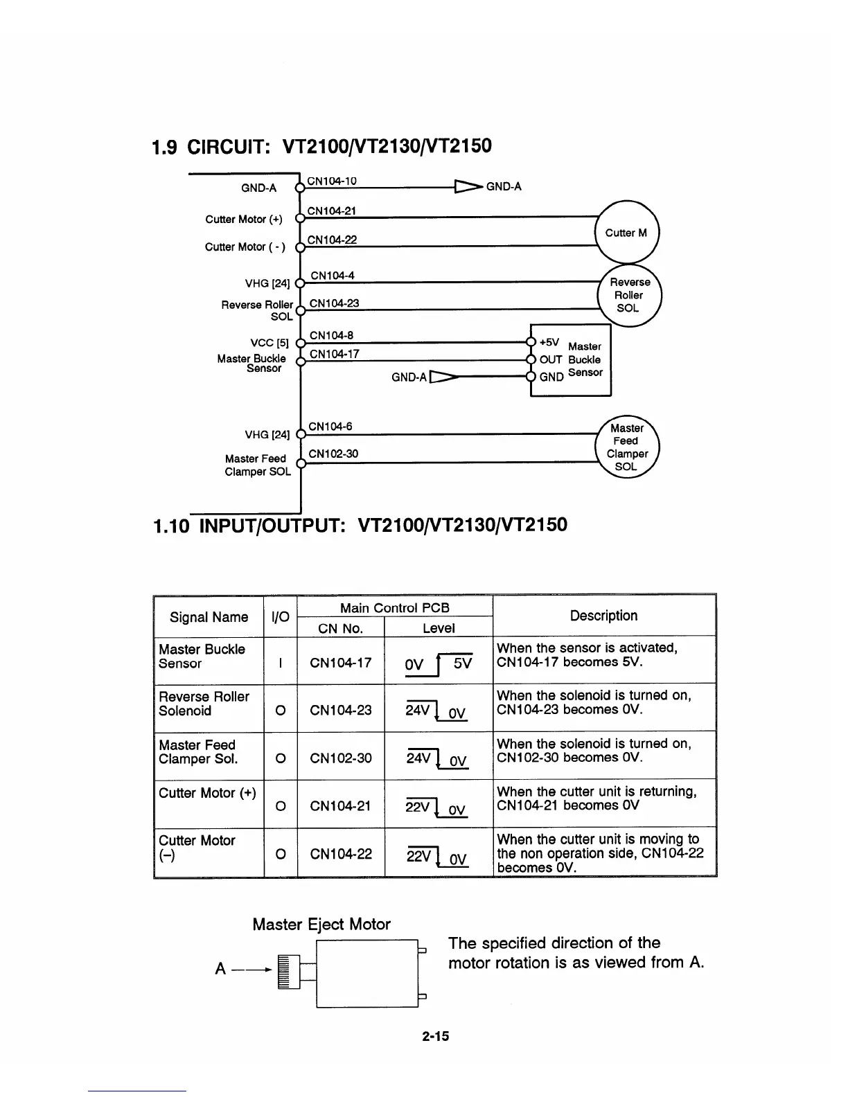
1.9 CIRCUIT: VT2100/VT2130/VT2150
GND-A
Cutter Motor (+)
CutterMotor ( - )
VHG [24]
Reverse Roller
SOL
Vcc [5]
Maste~~g~e
VHG [24]
Master Feed
Clamper SOL
CN104-10
O GND-A
CNI04-21
CN104-22
CN104-4
CN104-8
‘5V Master
CN104-17
OUT Buckle
‘ND-A=---+GNDsensOr
1
CN1 02-30
1.10 lNPUT/OUTPUT: VT2
Signal Name
1/0
Reverse Roller
Solenoid
o
Master Feed
Clamper Sol.
o
1
Cutter Motor (+)
o
,
Cutter Motor
(-)
o
J’
Roller
SOL
00/VT2
30/VT2150
Main Control PCB
Description
CN
No.
Level
When the sensor is activated,
CN104-17
Ov 1=
CN1 04-17 becomes 5V.
When the solenoid is turned on,
CN104-23
2X1 Ov
CN1 04-23 becomes OV.
When the solenoid is turned on,
CN102-3O
271 OV
CN1 02-30 becomes OV.
When the cutter unit is returning,
CN104-2I
Zq OV
CN1 04-21 becomes OV
When the cutter unit is moving to
CN104-22
Zq (-JV
the
nonoperationside, CN1 04-22
becomes OV.
Master Eject Motor
The specified direction of the
=
A
—~
motor rotation is as viewed from A.
3
2-15


 To Next Page