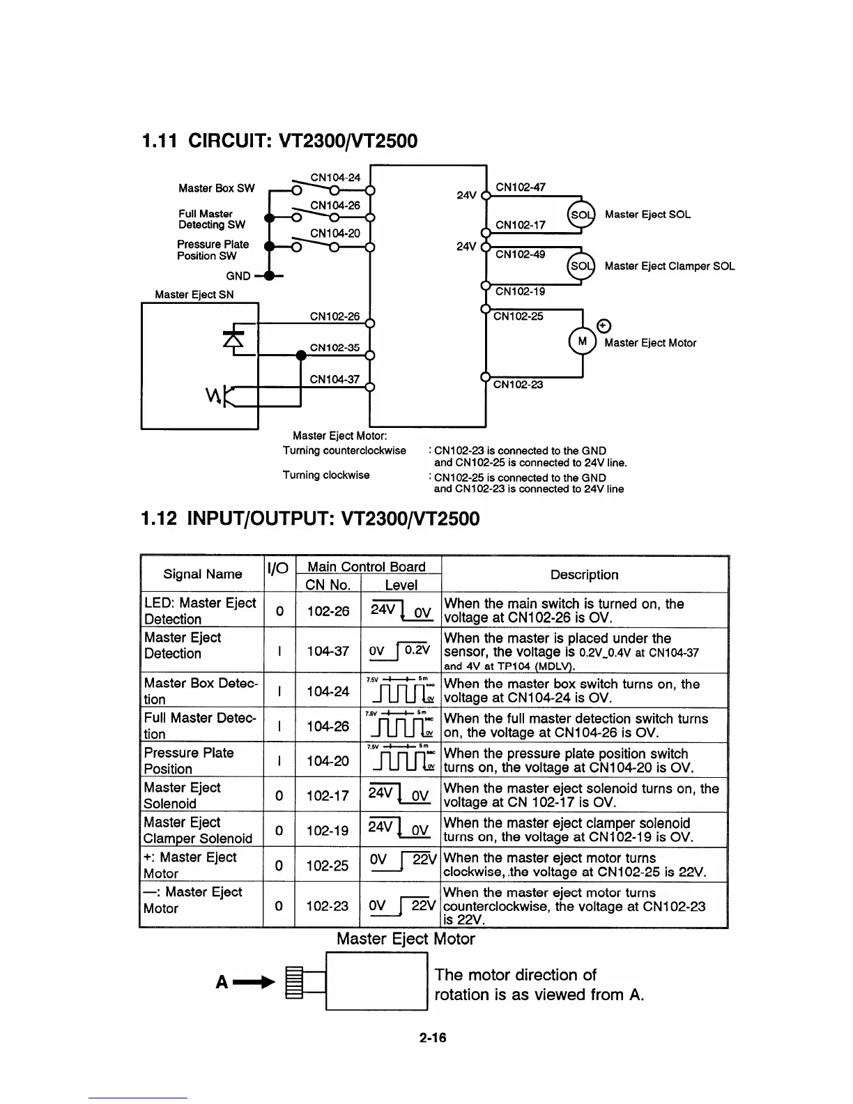
1.11 CIRCUIT: VT2300/VT2500
Master Box SW
-
Full Master
Detecting SW
~
--%=
Pressure Plate
Position SW
<
GND
Master Eiect SN
CN1 02-26
K
_ CN1 02-35
-
CN1 04-37
4K
24V
24V
Master Eject SOL
Master Eject Clamper SOL
[
Master Eject Motor:
CN1 02-25
+
o
+
M
Master Eject Motor
-
.
Turning counterclockwise
: CN1 02-23 is connected to the GND
and CN1 02-25 is connected to 24V line.
Turning clockwise
: CN1 02-25 is connected to the GND
and CN1 02-23 is connected to 24V line
1.12 lNPUT/OUTPUT: VT2300/VT2500
Signal Name
1/0
Main Control Board
Description
CN No, Level
LED: Master Eject
~
102-26
b=q Ov
When the main switch is turned on, the
Detection
voltage at CN1 02-26 is OV.
Master Eject When the master is placed under the
Detection
I 104-37
Ov [-v
sensor, the voltage is
0,2v-o.4v at CNI 04-37
and 4V at TP104 (M DLV).
Master Box Detec-
,
‘“v ~ 5m-
When the master box switch turns on, the
104-24
~w
voltage at CNI 04-24 is OV.
[ion
Full Master Detec-
,
7’6”~ 5“*
When the full master detection switch turns
lion
104-26 ~
w
on, the voltage at CN 104-26 is OV.
Pressure Plate
I 104-20
7“”~ 5“=
When the pressure plate position switch
‘osition
w turns on, the voltage at CN 104-20 is OV,
Master Eject
o 102-17 Z=q Ov
When the master eject solenoid turns on, the
Solenoid
voltage at CN 102-17 is OV.
Master Eject
o
102-19
Z=q Ov
When the master eject clamper solenoid
Clamper Solenoid
turns on, the voltage at CN1 02-19 is OV.
+: Master Eject
o 102-25
Ov Jp’v
when the master eject motor turns
Motor
clockwise, the voltage at CN 102-25 is 22V,
—: Master Eject
When the master eject motor turns
Motor
o 102-23
Ov /pz’v counterclockwise, the voltage at CN1 02-23
is 22V.
—.
Master Eject Motor
A+
=!
The motor direction of
rotation is as viewed from A.
2-16


 To Next Page