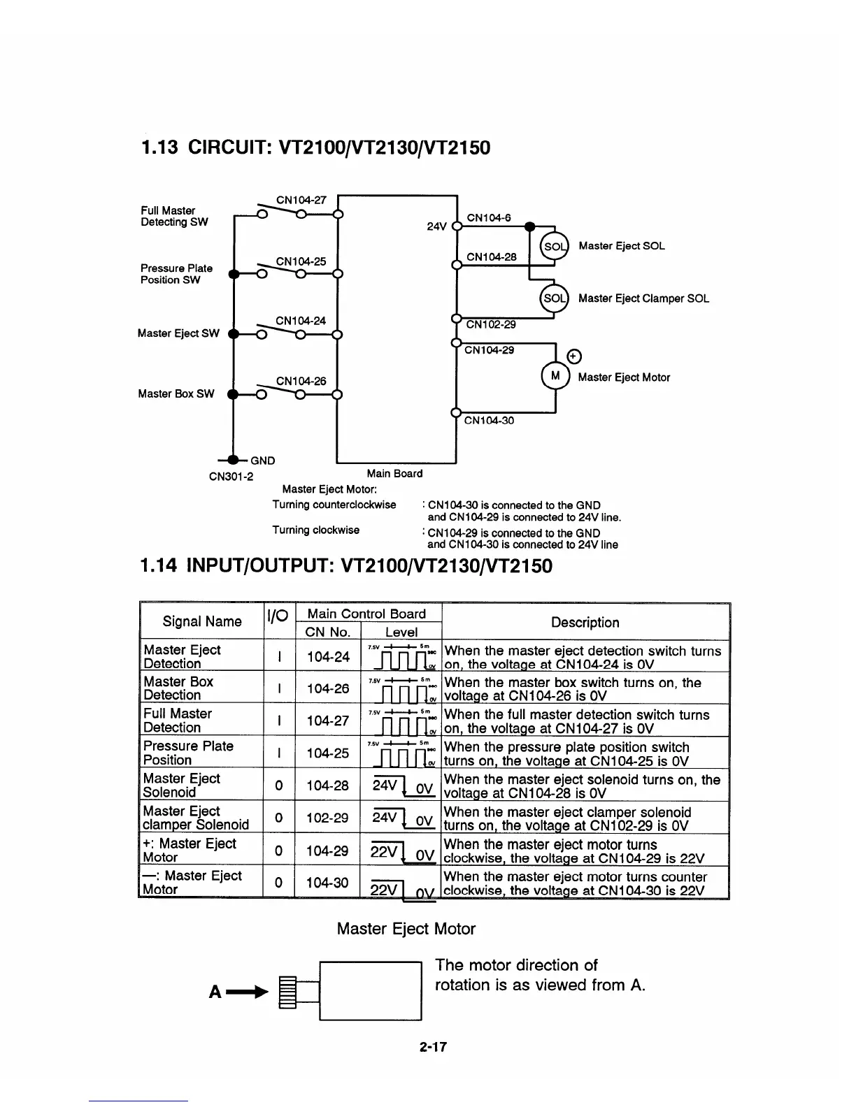
1.13 CIRCUIT: VT2100/VT2130/VT2150
Full Master
Detecting SW
Pressure Plate
Position SW
Master Eject SW
Master Box SW
-?5?5
-?5?5
- GND
CN301 -2
24V
C
c)
CNI 04-28
Main Board
Master Eject SOL
Master Eject Clamper SOL
c
‘CN104-3O
Master Eject Motor:
Turning counterclockwise : CN1 04-30 is connected to the GND
and CN1 04-29 is connected to 24V line,
Turning clockwise
: CN1 04-29 is connected to the GND
and CN 104-30 is connected to 24V line
1.14 lNPUT/OUTPUT: VT2100/VT2130/VT21 50
Eject Motor
Signal Name
Description
CN No. Level
I
Master Eject
I 104-24
‘“’v~ ‘“= When the master eject detection switch turns
Detection w
on, the voltage at CN 104-24 is OV
Master Box
I
104-26
‘“’v~ 5“=
When the master box switch turns on, the
Detection . voltage at CNI 04-26 is OV
Full Master
7,5v d——b 5m
i 104-27
When the full master detection switch turns
Detection
;
on, the voltage at CN1 04-27 is OV
Pressure Plate
I 104-25
‘“’v~ 5“- When the pressure plate position switch
Position
nw
turns on, the voltage at CN1 04-25 is OV
Master Eject
o 104-28
When the master eject solenoid turns on, the
2=1 Ov
voltage at CN1 04-28 is OV
Solenoid
Master Eject
o
102-29
When the master eject clamper solenoid
Z=q Ov
turns on, the voltage at CN1 02-29 is OV
clamper Solenoid
+: Master Eject
o
When the master eject motor turns
Motor
clockwise, the voltage at CN1 04-29 is 22V
—: Master Eject
o
When the master eject motor turns counter
Motor
~
..22VI
flv
,~4-30 is 22V
Master Eject Motor
2-17


 To Next Page