9. As the target VL and VD have been obtained, make sure that the flash and grid setting steps
are stabilized. If necessary, make fine adjustment so that no compensation is applied to the
flash and grid setting steps (no change of the flash and grid shift steps) as follows:
1) Select the [4-01] screen. (Be sure that all shift steps are 0.)
2) Press the Start key, and press the Clear/Stop key immediately after the 38th flash. The
machine stops after 40 flashes.
3) Read the flash and grid shift steps. If they are not 0 ± 2, add the value to the flash or grid
setting steps. Then, repeat the above step.
NOTE
• When you replace the OPC belt with a new one and the residual potential on the OPC is cleared,
reset the bias shift step to 0 as follows. This will let you know how many steps have been shifted up
or down at the next check of the data since the OPC belt replacement.
1) Select the [4-01] screen and read the bias shift step (compensated value). When the value is 0,
the check is completed.
2) Add (or reduce) the shifted-up (or down) value to (or from) the bias setting step using the value
change keys (▲▼) on the process control OFF screen.
• In the [4-01] screen, VR is measured and the bias shift step is changed when the Clear/Stop key is
pressed during free run.
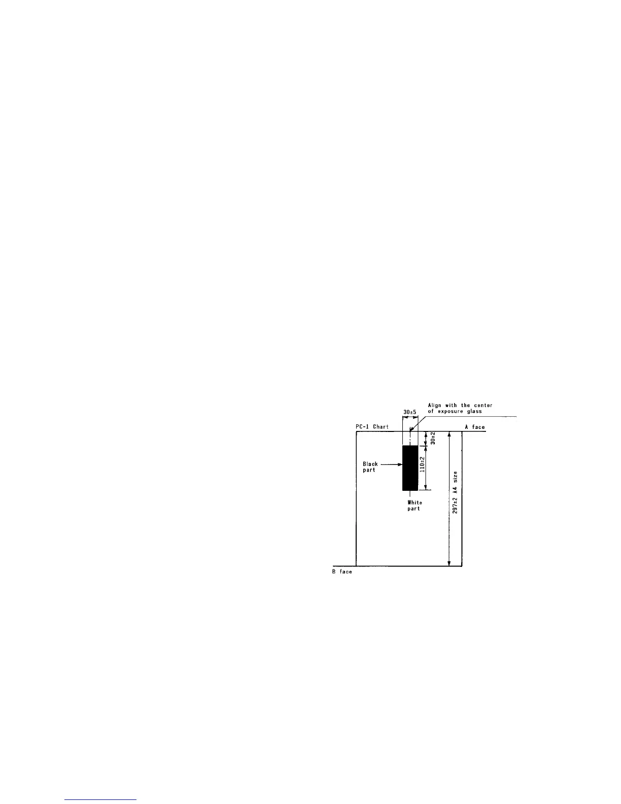
• The PC-1 chart is used for setting A. For the measurement of the black area of the chart, align the
center of face A (see figure) with the center of the original scale. For the white area, use face B.
1 July 1994 Setting A
5-7
 Loading...


