2.17.2 Basic operation
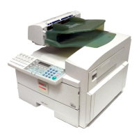
Inverter
When the finisher is used in the single side copy mode,
copies are always guided to the inverter tray as shown
by the dotted line in the above illustration. The copies
are inverted then delivered to the shift tray [F] with the
image side down. This means that copies are stacked
following page order on the shift tray.
In the duplex copy mode, copies are not inverted.
Copies are delivered to the shift tray with the first copy
side down. As a result, the duplex copies are stacked
following page order on the shift tray.
The inverter junction gate pawls [B] are switched by a
solenoid to direct copies to the inverter tray. The copy
entered into the inverter tray is stopped by the inverter
stoppers [E] and soon after, the inverter stoppers move
up to send the copy upward.
The inverter entrance [A], inverter 2nd [C], and inverter
3rd [D] sensors monitor the transportation of copies. All
the sensors perform both ON and OFF checks for paper
misfeed detection.
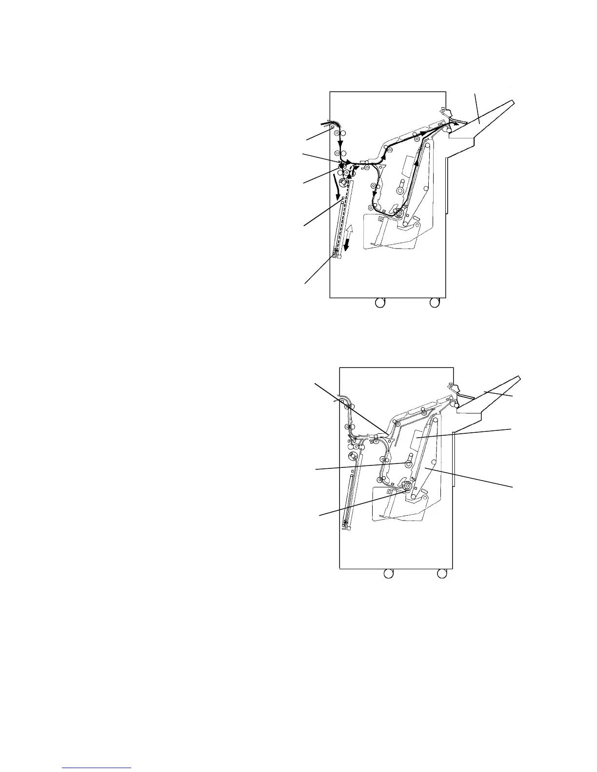
Finisher
After copy paper passes through the inverter unit, the
paper enters the finisher. If the sort/stack mode is
selected, the junction gate [A] directs the paper upwards
to transport it to the shift tray [B]. In these modes, the
shift tray is shifted side to side to stagger and separate
sets of copies. The amount of shift is approximately 30
mm. As the shift tray is shifted in a continuous copy run,
the copy is paused for 2 exposure flashes (if A4 paper is
used) to allow to complete the tray shifting. (To speed up
copying, the tray shifting can be canceled by pressing
the "No Staple" key twice.)
When the staple mode is selected, the junction gate
directs the paper below to transport the paper to the
jogger unit [C]. Each time a copy is delivered to the
jogger unit, the positioning roller [D], the alignment brush
roller [E], and the jogger fences [F] square the stack of
copies. After the final copy of the set is squared, the set
is stapled, and then delivered to the shift tray.
NOTE:
The finisher part is completely the same as the A354 finisher,
except for the top exterior cover and two stands at the bottom. The
EPROM on the finisher control PCB is also different. The inverter
part is unique to this finisher.
[A]
[F]
[B]
[C]
[D]
[E]
[A]
[C]
[B]
[D]
[E]
[F]