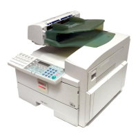
2.17.3 Inverter junction gate operation
In the single side copy mode, if one of the finishing
modes is selected, the inverter junction gate solenoid [A]
is energized when the copier exit sensor (the eject
junction sensor) detects the first copy.
The junction gate pawls [B] are switched so that copy
paper is directed into the inverter tray (downward). The
inverter guide brush roller [C] is always rotating while the
finisher is in operation, and it presses the copy paper
against the paper guide plate and helps guide the copy
paper to the inverter tray.
Soon after the copy paper enters the inverter tray, it is
moved up and returned to the inverter guide brush roller
by the inverter stopper operation. (See the next section
for the inverter stopper operation.) Although the inverter
guide brush roller is rotating against the paper
transportation at this time, the copy paper passes the
roller and is sent to the finisher part because of the soft
brush surface of the inverter guide brush roller and a
clearance between the roller and paper guide plate.
In the duplex copy mode, copies are sent to the finisher
regardless of the finishing mode selection. In this case,
the inverter junction gate solenoid remains
de-energized, so that the junction gate pawls guide the
copies to the right. The copies are sent to the finisher
part and fed out to the shift tray without paper inversion.
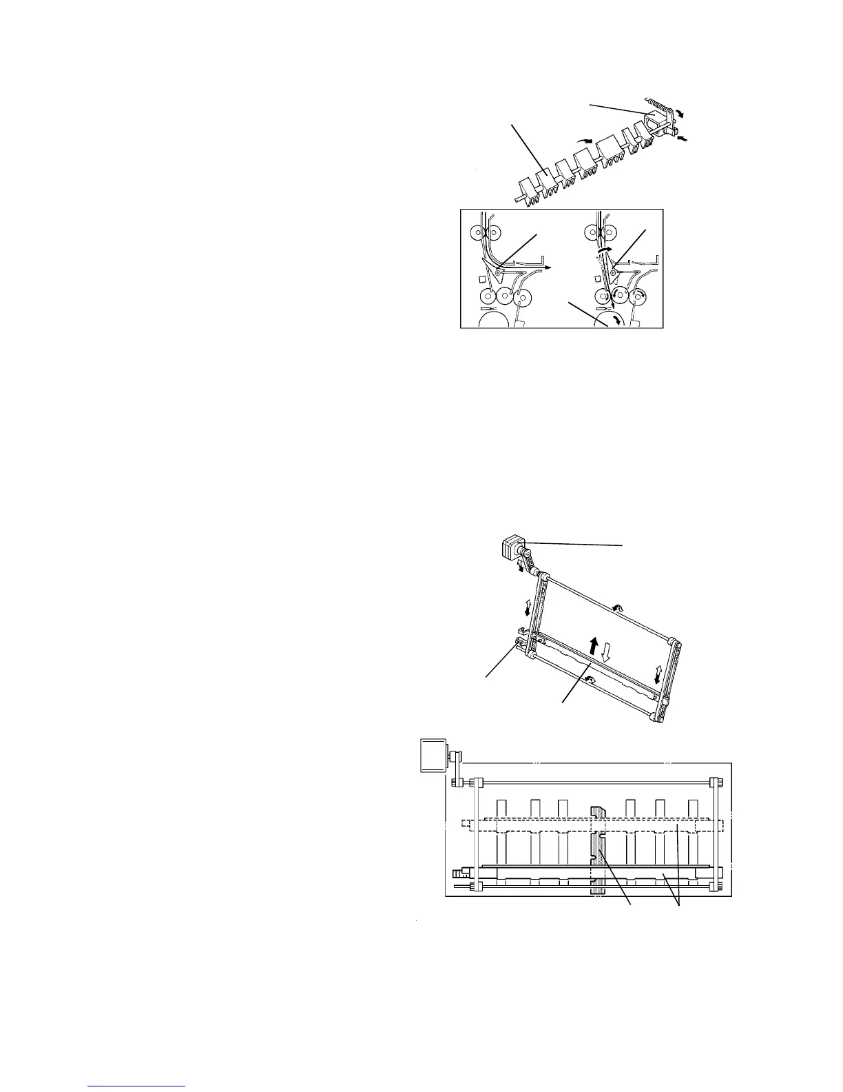
2.17.4 Inverter stopper operation
When the finisher ON signal is sent to the inverter
control PCB from the copier, the stopper plate [C] is
moved up from its home position by the stopper drive
motor [A] (a stepper motor) via timing belts. The stop
position of the stopper plate is set by the pulse signal
from the inverter control PCB. (The pulses are
determined based on the paper size signal from the
copier.) The stopper plate waits for the paper entering
into the inverter tray at the stop position.
A decal [D] indicating paper sizes is attached in the
inverter tray to check the stop position of the stopper
plate for each paper size.
After copy paper enters the inverter tray, the leading
edge of the paper hits the inverter stoppers, which are
fixed in the stopper plate and sponge material to absorb
the shock of the hit. Soon after this, the stopper drive
motor moves up the stopper plate slightly. The copy
paper is moved up and returned. Then the stopper plate
is returned to the stop position. The stopper plate
repeats this operation for each paper entering the
inverter tray.
When the finisher ON signal turns OFF, the stopper
drive motor rotates in the opposite direction to return the
stopper plate to its home position. The stopper home
position sensor [B] detects the feeler fixed on the
stopper plate.
[D] [C]
[A]
[B]
[C]
[B]
[B]
[A]
[B]
[C]