2.2.8 Flash power supply
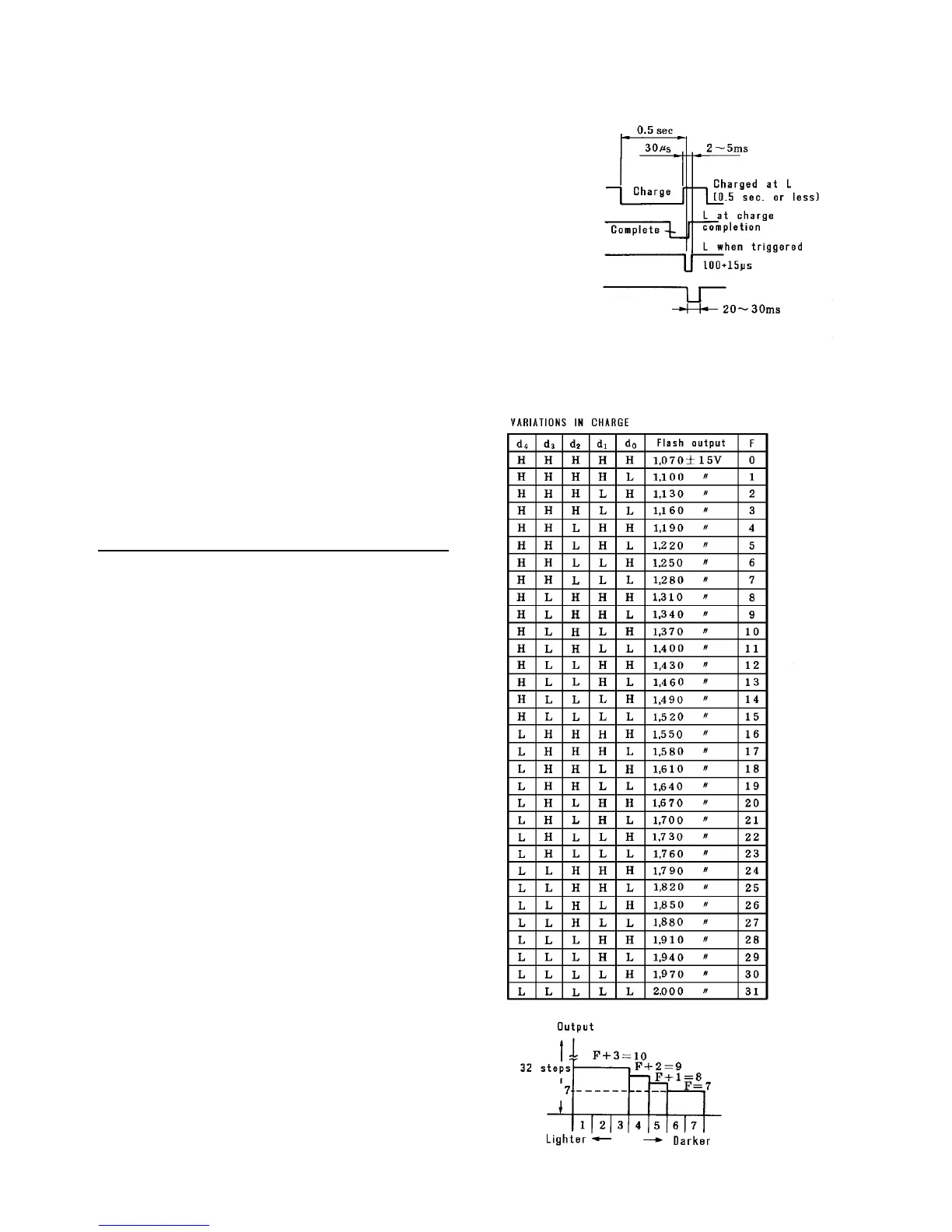
Flash timing
The flash power supply is controlled by signals from the
main control board, and charge voltage is varied in 32
levels with bit signals.
Flash output compensation
Output can vary according to these conditions:
• Image density level
• Magnification
• Correction by process control
Compensation by image density level
Level 6, 7 …… Standard step (F)
Level 5 …… F + 1 step
Level 4 …… F + 2 step
Level 1, 2, 3 …… F + 3 step
The standard step (F) is the flash output voltage that is
determined by the process control.
Example
If the standard step F is 7, this means that the flash
output voltage is 1,280 volts as you see in the table.
The flash output steps for the image density levels
are as shown in the right figure.
a. Charge ON signal
(CN2-4)
b. Charge complete
signal (CN2-6)
c. Flash ON signal
(CN2-6)
d. Flash detection
signal (CN2-7)
L at flash
detection