1.8 LCT Installation
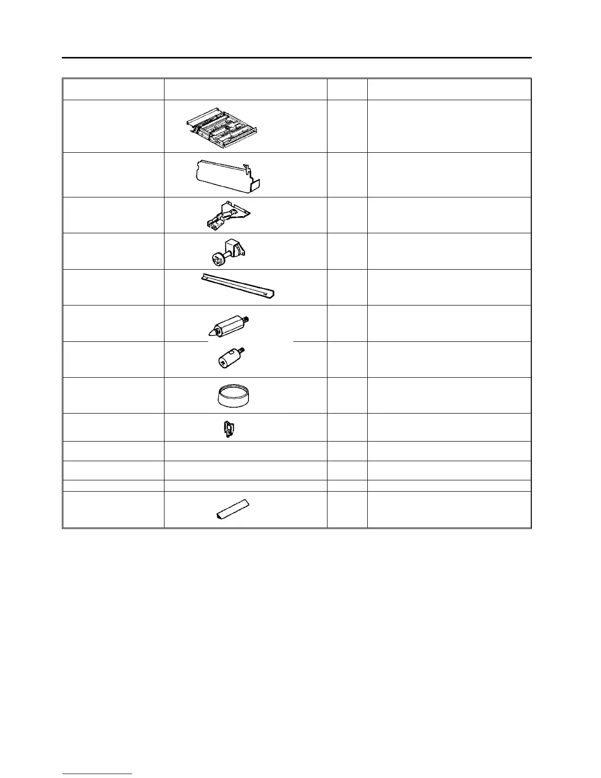
1.8.1 Accessories list
Name Diagram Quantity Use
Horizontal transport unit 1 This is the relay transport part between LCT
and the copier and is attached to the copier.
Rear side fence 1 Rear side fence for the tray when 11" x 8 1/2"
or 14" x 81/2" size paper (A4 size for the
U.S.A. version machine) is used. (Not
required if such paper is not used.)
Lock lever assembly 1 Guide plate open/close lever to be attached
to the horizontal transport unit.
Knob assembly 1 Manual drive knob to be attached to the
horizontal transport unit.
Sub-tray auxiliary plate 1 Auxiliary stay when the sub-tray is fitted to
LCT. (Not required when the finisher is used.)
Docking pin 2 This is used for docking between LCT and
the copier and is attached to the copier.
Fixing stepped screw 2 Stud to install the sub-tray auxiliary plate.
(Not required if the finisher is used.)
Leveling shoe 4 For the docking position adjustment.
Wire saddle 2 For clamping the power harnesses of the
LCT and finisher to the exterior cover.
Pan head machine screw M4 x 6 6 For fixing the horizontal transport unit, lock
lever and knob.
Grounding screw M4 x 8 1 For fixing the protective earth wire of the
power supply harness (The copier side).
Plated screw M4 x 6 2 For fixing the sub-tray auxiliary plate.
Upper cover stopper 1 To prevent fall of something placed on the
LCT upper cover when the cover is opened.
NOTE:
When the optional finisher is not used, the
sub-tray (P/N-A0291460) must be ordered and
used with the LCT.
Zinc plated