3.8 Finisher Electrical Components
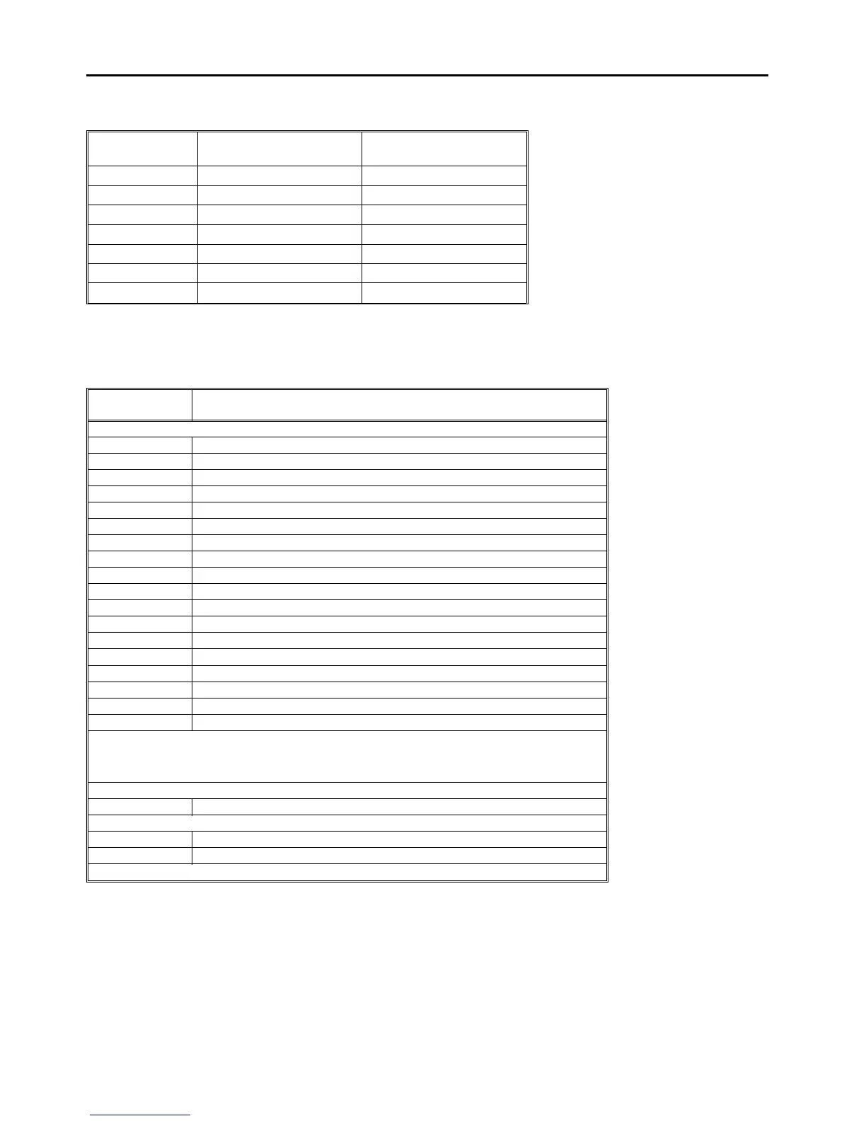
3.8.1 Test point table
Number Function Location
TP1 24 V Finisher Control PCB
TP2 GND Finisher Control PCB
TP3 5 V Finisher Control PCB
TP100 GND Inverter Control PCB
TP101 5 V Inverter Control PCB
TP102 24 V Inverter Control PCB
TP103 Not used Inverter Control PCB
3.8.2 LED table
LED No. ON Status
Finisher Control PCB
LED 1 Stack feed-out belt H.P. sensor is not actuated.
LED 2 Jogger unit connector is not completely set.
LED 3 Stapler H.P. sensor is actuated.
LED 4 Jogger H.P. sensor is actuated.
LED 5 Jogger unit paper sensor is activated.
LED 6 Jogger unit entrance sensor detects paper.
LED 7 Shift tray lower limit sensor is actuated.
LED 8 Stack height sensor 2 is actuated.
LED 9 Exit unit H.P. sensor is actuated.
LED 10 Exit unit half turn sensor is not actuated.
LED 11 Stack height sensor 1 is actuated.
LED 12 Shift tray half turn sensor is actuated.
LED 13 Exit sensor detects paper.
LED 14 Finisher entrance sensor is activated.
LED 15 Hammer H.P. sensor detects the hammer.
LED 16 Staple end sensor is activated.
LED 17 OFF: Motor speed is too low. ❇Note
LED 18 OFF: Motor speed is too high. ❇Note
NOTE: In the motor test mode, the finisher transport motor, stack feed motor, and exit drive motor
speeds are adjusted automatically in order. While each motor is adjusted, if the motor speed is
normal, LED17 and LED18 light. If the motor speed is too high, only LED17 lights. If the motor speed
is too low, only LED18 lights.
Transport Drive Motor Control PCB
LED 1 Finisher transport motor speed is normal.
Inverter Control PCB
LED 100 Not used.
LED 101 Not used.
NOTE: VR100 and VR101 are not used either.
Finisher Electrical Components 1 July 1994
3-10