30.
Remove the rear right cover (2 screws).
31.
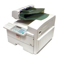
Be sure that the proper connector of the harness
from the timer board is set. The color of each
connector means the following:
Black: for 380 or 220V power supply
Red: for 400 or 230V power supply
Yellow: for 415 or 240V power supply
32.
If the connector setting does not meet the power
supply, connect an appropriate connector.
33.
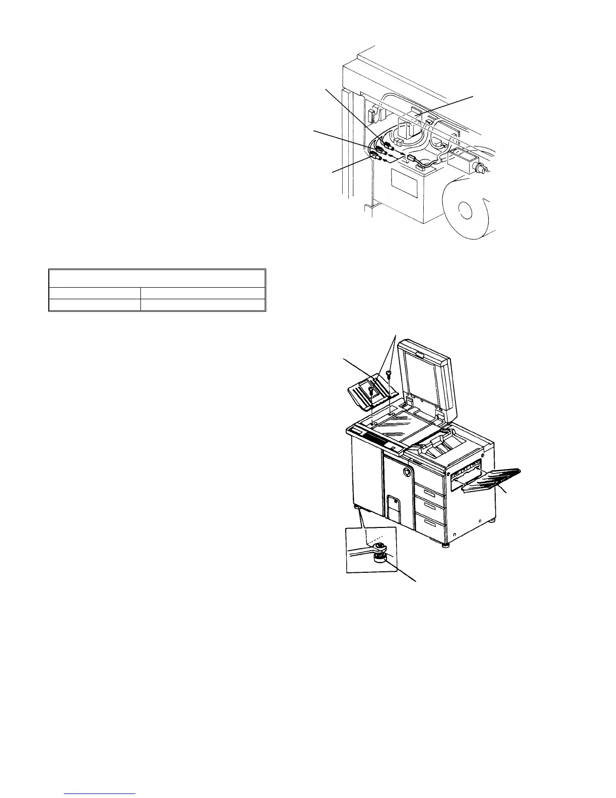
Set the leveling shoes (accessories) to level the
machine.
STANDARD
Difference, front to rear Within 5 mm
Difference, left to right Within 5 mm
CAUTION
Using a level gauge, level the machine flat on
the floor. This is mainly to prevent affecting the
tracking operation of the OPC belt.
34.
Install the exterior covers.
NOTE
Do not install the exterior covers at this stage if the
finisher or LCT is to be installed.
35.
Fit the original stacker (accessory) and sub-tray
(must be ordered separately if necessary). To fit
the original stacker, use screws which secured the
upper left cove (M4 x 12 plated screw).
36.
Put the original back fence (accessory) on the
original stacker.
NOTE
The sub-tray is not required if the finisher is used.
It is installed in the LCT if the LCT is used and the
finisher is not.
Timer board
transformer
Red
connector
Black
connector
Yellow
connector
Original stacker
Sub-tray
Leveling shoe
Screws securing
upper left cover
1 July 1994 Copier Installation
1-13