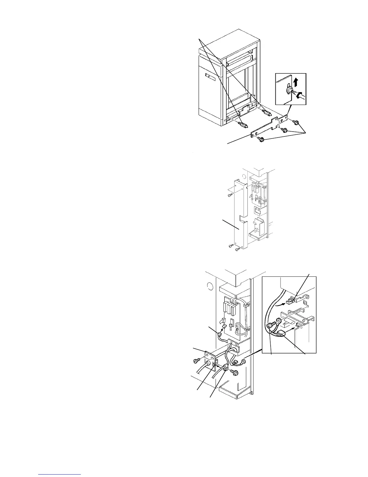
1.9.4 Docking preparation
NOTE
This procedure is required only when the LCT is
used with the finisher.
1. Remove the right cover (5 screws) then remove
the two blind caps.
2. Install the two docking pins (accessory).
3. Remove the 4 screws.
4. Install the docking support plate (accessory).
Tighten the 4 screws removed in the above step
while holding the plate up.
NOTE
The docking support plate is required to strengthen
the docking parts in the LCT. The left side of the
finisher is supported only by the two docking pins.
5. Reinstall the LCT right cover.
1.9.5 Harness connection and docking
1. Remove the inverter rear cover (4 screws).
2. Pass the power cord and optical fiber cable
(connected to the copier side) through the harness
docking hole. Then, secure the harness bracket
with the two M4 x 6 screws (accessories). At the
same time, bring the optical fiber cable into the
clamp in the harness bracket and secure it with the
wire clamp and panhead screw with washer
(accessories).
CAUTION
Clamp the optical fiber cable in the harness
bracket so that the portion between the finisher
and LCT (or copier) is longer than that of the
power cord.
3. Connect the power cord connector to the dc power
supply PCB and the optical fiber cable connector
to the inverter control PCB. Then, secure the
grounding wire with the M4 x 8 grounding screw
(accessory) as shown. The grounding screw must
be firmly secured in place with a force of 10 to 15
kgfcm torque.
CAUTION
The optical fiber cable connector must be set to
the socket on the PCB properly as it has the
setting direction.
4. Bind the power cord with the wire clamp.
5. Reinstall the inverter rear cover.
Screws
Docking support
plate
Docking pins
Inverter
rear cover
Grounding
screw
Power cord
connector
Wire
clamp
Harness
docking hole
Wire clamp
Clamp
Harness
bracket
Optical
fiber cable
connector