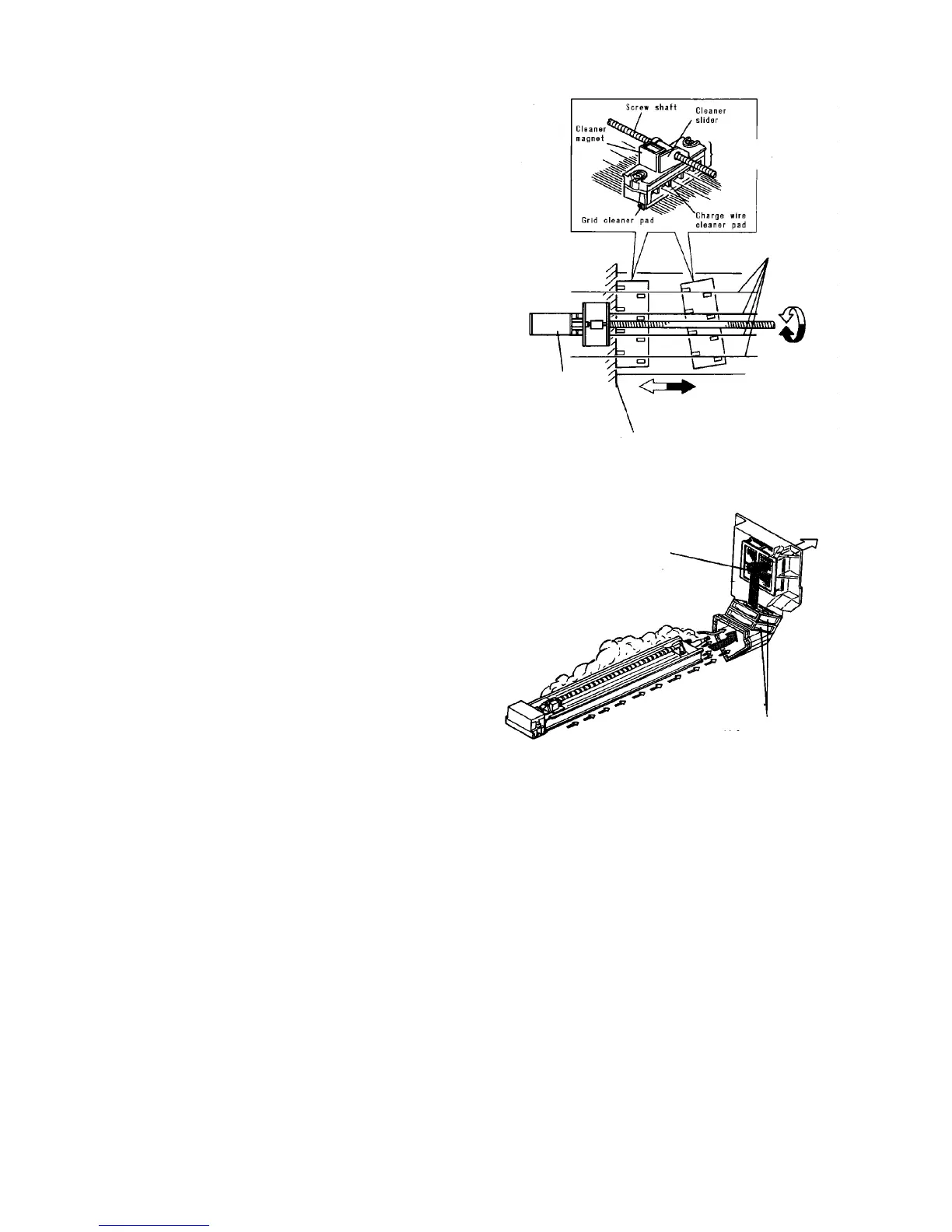
2.4.3 Cleaner mechanism
The cleaner cleans the charge wires and grid wires to
prevent fluctuation in photoconductor surface potential
caused by contamination.
The cleaner unit is set with the feed screw and can be
moved to the front and rear of the unit by turning the
cleaner motor.
After the cleaner unit leaves its home position, the
cleaner magnet is attracted and in contact with the
cleaner slider. This makes the cleaner unit slanted so
that the cleaner pads touch the charge wires. At the
home position, attraction on the magnet is released by
contact of the cleaner unit and the end block. The
cleaner pad separates from the charge wires to prevent
a change in the wire position from causing a contact with
the pad.
Cleaning is conducted when the main switch is turned
on after 20,000 or more copies have been made.
2.4.4 Ozone exhaust mechanism
If ozone generated by discharge is allowed near the
photoconductor, image smearing can result. To prevent
the build up of ozone near the photoconductor, a duct
and two fans are provided.
The ozone gas is drawn and filtered by the ozone filter
on the rear cover and discharged as clean air. When the
main switch is ON, the two motors start. When the main
switch is turned OFF, these motors continue to run for
about 30 minutes. This is controlled by the timer board.
The outside fan keeps on turning for 8 to 10 hours
more. It is powered by the internal battery.
Cleaner motor
Home position
Forward
Charge corona wire
Cleaner
unit
Ozone filter
Ozone exhaust fan