❈2 Just before the machine enters the copy stand-by
condition, the ID sensor pattern is made and
‘ measured.
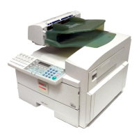
The first charge is to make dummy potential on the
OPC surface. The dummy charge is made using a
grid voltage which is about 10 steps lower than that
during copying. The preceding lowered grid voltage
for making the ID sensor pattern is stored and the
same value is used for the dummy charge this time.
The dummy potential is measured by the potential
sensor and erased by the eraser. The measured value is
compared with the selected ID sensor pattern level in
service tool [4-02]. Then, the grid voltage is
compensated so as to be the same potential as the
selected pattern level, and the second charge is
conducted. The electric latent image of 420 x 50 mm is
formed by erasing unwanted areas, and it is developed
to produce the ID sensor pattern.
When the dummy potential is the same as the selected
ID sensor pattern level, the second charge is not done
and the first (dummy) charge is used to make the ID
sensor pattern.
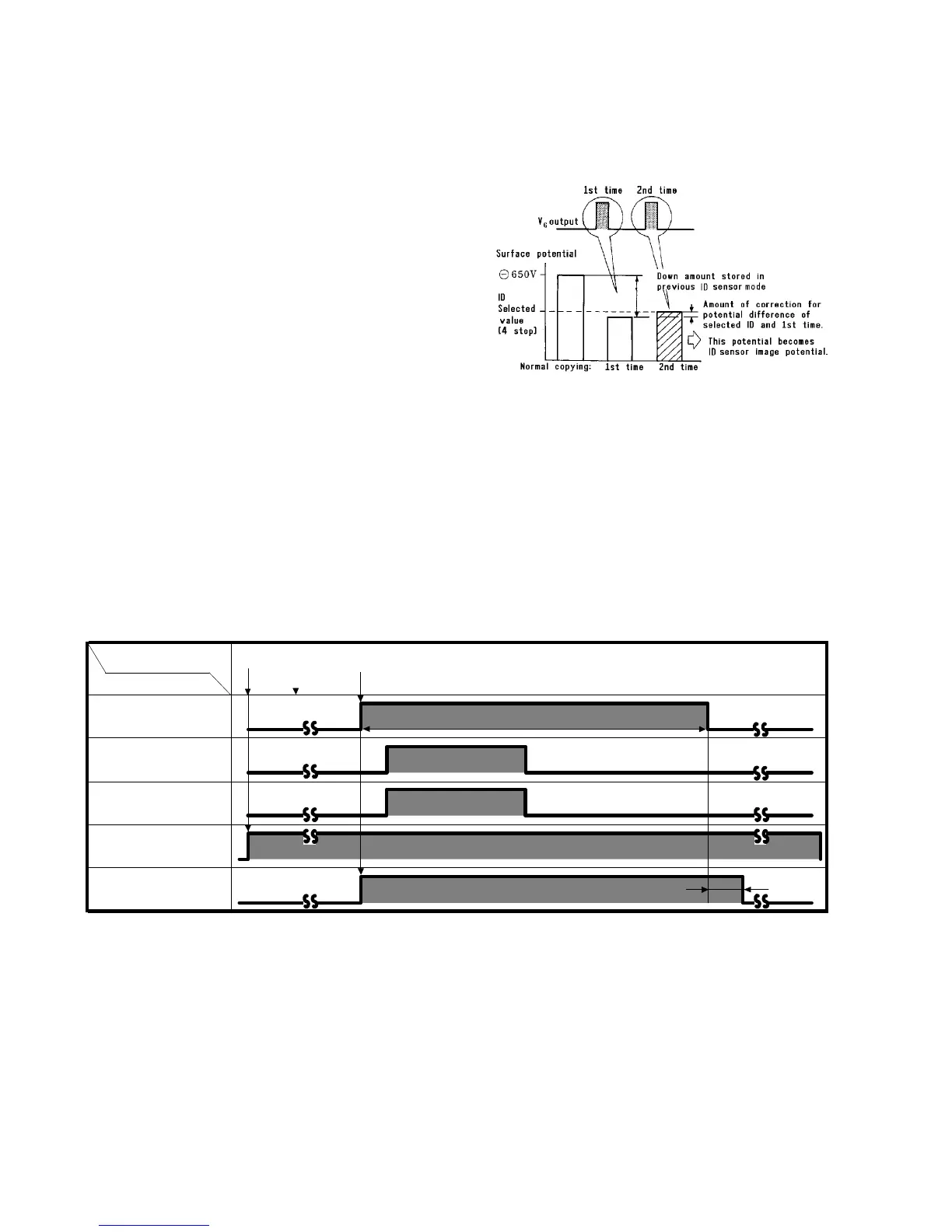
Operation during copying
(Single copying in the platen cover mode)
Timing
Item
60 sec
422
422
2,160
2,160
0
5,240
Main motor
Charge output
Grid output
Ozone exhaust
fan 1
Ozone exhaust
fan 2
Power supply
connection
Start key ON
[Pulse]
Main SW ON