4.40 PCB RR-120 MOTHERBOARD REF 5010-120
Voltages
1. Before adjustment switch the Photometer 5010 V5+ off. Open the device. Open the photometer
regarding safety rules of chapter 1 of this service manual (chapter 5.1 Opening).
2. The device plug of the mains cable must be put into the mains cable socket at the back of the device
and the mains plug of the mains cable must be put into a grounded mains socket.
3. Switch the device on.
4. Use DVM for measuring ± 12 V
DC
.
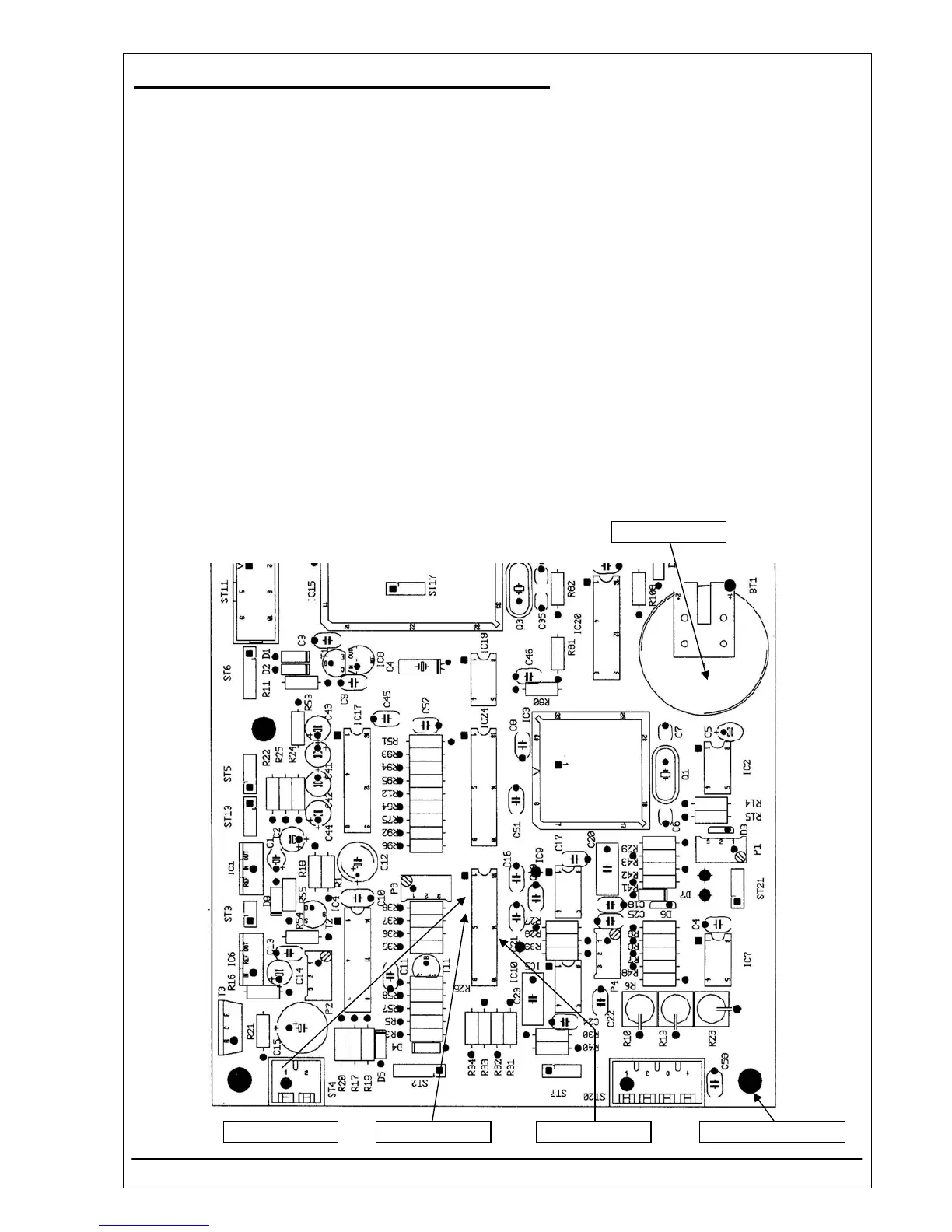
5. Connect the negative lead of DVM to the ground connector (soldering connector).
6. Connect the positive lead of DVM to the pin 3 of IC10.
7. Check the voltage + 5 V
DC
(tolerance ± 5%).
8. Connect the positive lead of DVM to the pin 4 of IC10.
9. Check the voltage - 12 V
DC
(tolerance ± 5%).
10. Connect the positive lead of DVM to the pin 14 of IC10.
11. Check the voltage + 12 V
DC
(tolerance ± 5%).
12. Connect the positive lead of DVM to the battery BT1.
13. Check the voltage + 3 V
DC
(tolerance ± 10%).
+ 3 V
DC
± 10%
- 12 V
DC
± 5%+ 5 V
DC
± 5% +12V
DC
± 5% Ground connector
RIELE BERLIN Photometer 5010 V5+ 4.40.4 17.03.2009