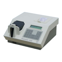
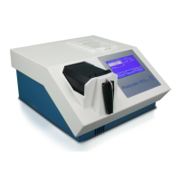
4.1 MAINS POWER CIRCUIT
Function Description
The mains power circuit shows the design of the complete primary circuit. Components of the circuit are:
• Mains connector
• Mains fuses Fa and Fb REF 5010-018
• Mains switch
• AC/DC power supply REF 5010-016 (terminal block with 7-pins)
or REF 5010-086 (terminal block with 9-pins)
• Line filter
• Ground connection
• Wires
Location
Backside of Photometer 5010 V5+, base plate
Replacement
• see chapter 5.1 Opening
• see chapter 5.2 Separating top case and bottom case
• see chapter 5.3 Base plate
• see chapter 5.6 Power supply
Installation
For installation proceed in reverse order.
Fuses
Between the mains switch and the mains cable connector there is a cartridge with two fuses Fa and Fb with
following specifications:
• dimensions [mm] : 5 * 20
• standard: IEC 60127-2/V
• time-current characteristic: time lag (T)
• voltage rating: 250 V
• rated current: 1.6 A
• marking: T 1.6 A H
RIELE BERLIN Photometer 5010 V5+ 4.1.1 18.08.2010