AX10 Palletizing Solution
1. Connect each box sensor as described in the Box Sensor (Single Box Type) section.
2. Take note of the digital input terminal to which each box sensor is connected.
NOTICE
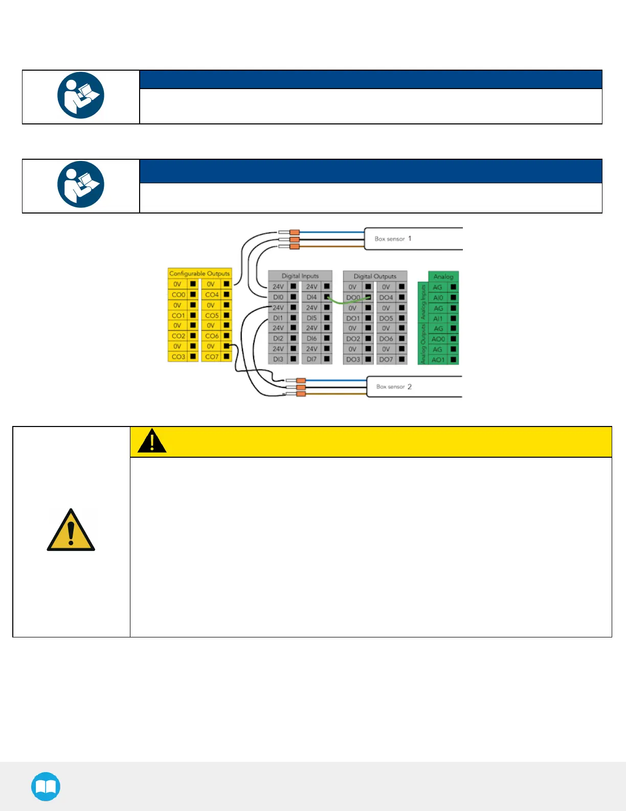
The figure below shows an example in which the digital input terminal for box sensor #1 is DI0, and
the digital input terminal for box sensor #2 is DI1.
3. Lay a wire between an unused digital input terminal and an unused digital output terminal (this is depicted by the green wire
in the figure below).
NOTICE
In the figure below, digital output DO0 will activate digital input DI4.
Fig. 3-4: Wiring Box Sensors for Multiple Box Types
CAUTION
Connection Between Digital Input and Digital Output
This wiring procedure is the hardware step of the multi-pick feature, and will not make the feature
functional on its own unless it is properly programmed in the robot software. Please refer to the
Palletizer Node With Multi-Pick Feature section to go through the software steps and enable the multi-
pick feature.
The end result of this wiring procedure is for the robot to receive a combined signal indicating that both
box sensors have been activated simultaneously, and that it can pick up the group of boxes altogether.
And so, when both box sensors detect a box, the digital output (DO0 in the above figure) will send that
combined signal to the robot.
For that reason, the digital output must be connected to digital input (DI4 in the above figure) for it to
be usable in the robot program.
60