Robustel R5020 Hardware Manual
RT064_HM_R5020 8/11
Press and hold the RST button for 2~ 5 seconds under the operating status.
Restore to default
configuration
Press and hold the RST button for 5~10 seconds, the RUN LED starts blinking quickly, the router will restore to default
configuration.
Restore to factory
default settings
Once the operation of restoring default configuration is performed twice within one minute, the router will restore to factory
default settings.
Note: The more details please refer to RT123_SM_RobustOS Software Manual, 2.3 Factory Reset.
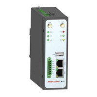
4. Ethernet Ports. There are four Ethernet ports on R5020, including ETH0 (Optional POE supported), ETH1,
ETH2, ETH3. The ETH0 on the router can be configured as a WAN port, while ETH1, ETH2 and ETH3 can only
be configured as a LAN port. By default, ETH1, ETH2 and ETH3 are lan0, and their IP are
192.168.0.1/255.255.255.0.
Connection is established
Data is being transferred
Connection is not established
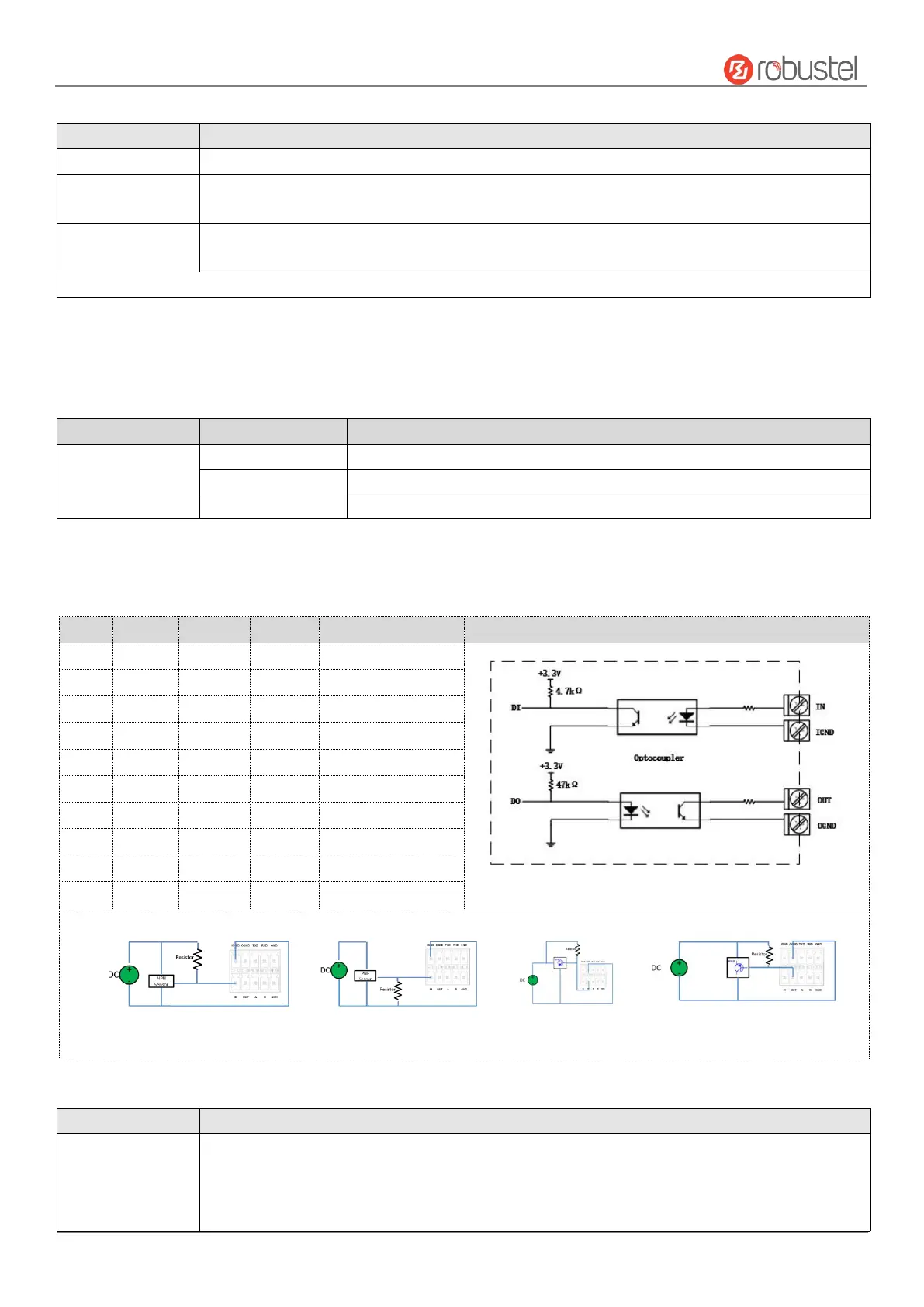
5. Digital IO & Serial Port. 2x5PIN 3.5mm pitch terminal block, 1 set of DO, 1 set of DI, 1 x RS232 and 1 x RS485.
DI signal access, can be used for NPN/PNP type sensor signal or switch signal acquisition. DO signal output,
can be used for NPN/PNP sensor control, please connect signals by referring to typical applications.
Internal diagram of DI&DO
Typical Application:
DI connected with NPN sensor DI connected with PNP sensor DO Driven NPN Triode DO Driven PNP Triode
Note: The external power supply DC voltage range is 3V~30V.
USB interface is used for batch firmware upgrading, but cannot be used for sending or receiving data from slave devices which
connected to it. You can insert a USB storage device into the router’s USB interface, such as a U disk or a hard disk. If there have a
supported configuration file or a router firmware in this USB storage device, the router will automatically update the
configuration file or the firmware. For more details, please refer to RT123_SM_RobustOS Software Manual.