Rockwell Automation Publication 1769-UM021I-EN-P - May 2018 195
Use I/O Modules with CompactLogix 5370 L2 Controllers Chapter 8
4. Repeat step 3 for all embedded I/O wires that are needed in your
application.
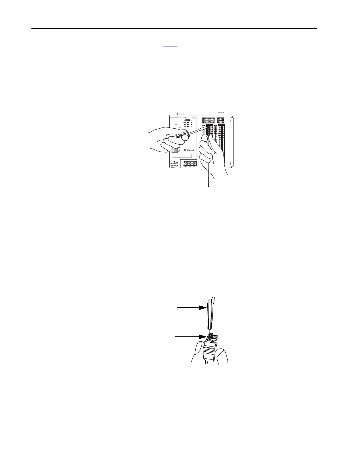
To remove a wire from the removable connector, complete these steps.
1. Verify that the control system is not powered.
2. Use a small screwdriver to push the spring release clip and pull out the
wire.
You can use a continuity tester to determine if the connection point is
operating correctly, that is, the connection point is a complete circuit. You use a
continuity tester if any issues arise with a removable connector and you suspect
that a connection point can no longer be functioning as a complete circuit.
The indication mechanism, for example, a light that illuminates on the tester,
varies by continuity tester. The following example graphic shows a continuity
tester with one connection point. In this case, if the circuit is operating
correctly, the indicator light turns on.
Insert a continuity tester into the suspected I/O connection point as shown in
the following graphic.
Continuity Tester
Small hole on
opposite from
termination point
in removable
connector.
 Loading...


