56 Rockwell Automation Publication 1769-UM021I-EN-P - May 2018
Chapter 3 Install the CompactLogix 5370 L2 Controller
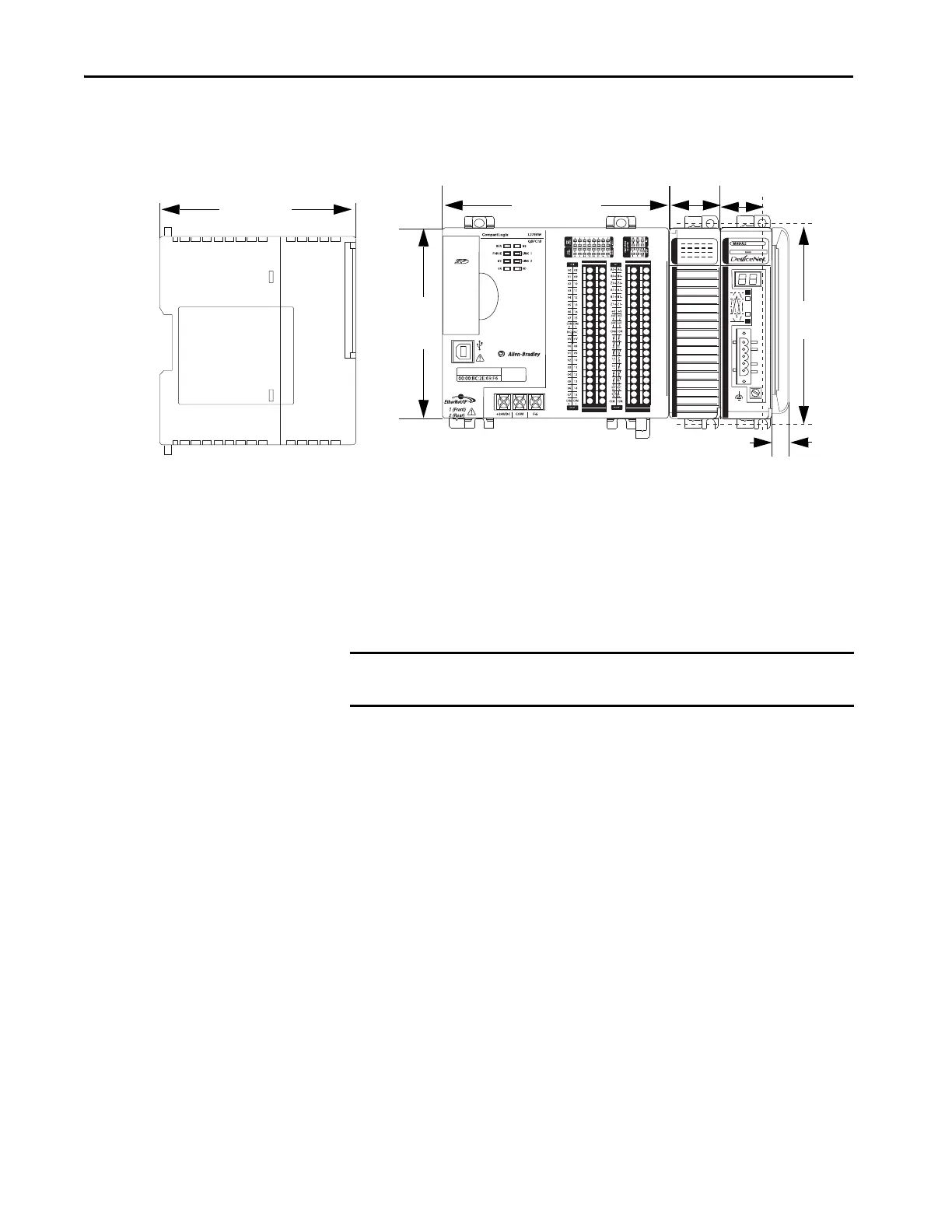
This graphic shows the system dimensions for the 1769-L27ERM-QBFC1B
controller with expansion modules installed.
Mount the Controller on a Panel
Use two M4 or #8 pan head screws to mount the controller. Mounting screws
are required on every module. Use this procedure to use the assembled modules
as a template to drill holes in the panel.
1. On a clean work surface, assemble no more than three modules.
2. Use the assembled modules as a template and carefully mark the center
of all module-mounting holes on the panel.
3. Return the assembled modules to the clean work surface, including any
previously mounted modules.
4. Drill and tap the mounting holes for the recommended M4 or #8 screw.
118.00 mm
(4.65 in.)
35.00 mm
(1.38 in.)
105 mm
(4.13 in.)
140.00 mm
(5.51 in.)
18.00 mm
(0.71 in.)
126.6 mm
(4.98 in.)
25.00 mm
(0.98 in.)
IMPORTANT Due to module mounting hole tolerance, it is important to follow these
procedures.
 Loading...


