85
Appendix
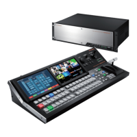
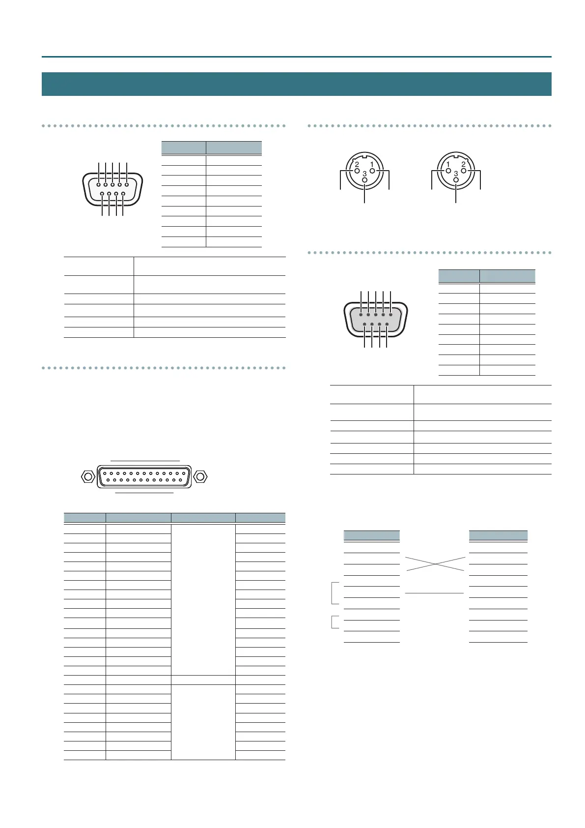
V-1200HD Connector Specications
RS-422 Connector
D-Sub 9-pin (female)
Pin number Signal name
1 GND
2 TxD+
3 RxD-
4 GND
5 NC
6 GND
7 TxD-
8 RxD+
9 GND
Transmission method
Start-stop synchronization (asynchronous mode),
full-duplex
Communication speed
(baud rate)
9,600 bps/38,400 bps (Set this according to the
status of communication with the remote cameras.)
Parity None
Data length 8 bit
Stop-bit length 1 bit
Flow control None
TALLY/GPIO Connector
5 Tally/control output connector specications
Maximum input: 12 V/200 mA
Open-collector type
5 Control input connector specications
Trigger method: No-voltage contact (make-contact) triggering
Contact capacity: DC 24 V 0.1 A or higher
Input method: Photocoupler
D-Sub 25-pin (female)
113
1425
Pin number Connector name Function Default
1
OUTPUT 1/GPO 1
Tally output/
control output
SDI 1 PGM
2
OUTPUT 2/GPO 2 SDI 1 PST
3
OUTPUT 3/GPO 3 SDI 2 PGM
4
OUTPUT 4/GPO 4 SDI 2 PST
5
OUTPUT 5/GPO 5 SDI 3 PGM
6
OUTPUT 6/GPO 6 SDI 3 PST
7
OUTPUT 7/GPO 7 SDI 4 PGM
8
OUTPUT 8/GPO 8 SDI 4 PST
9
OUTPUT 9/GPO 9 SDI 5 PGM
10
OUTPUT 10/GPO 10 SDI 5 PST
11
OUTPUT 11/GPO 11 SDI 6 PGM
12
OUTPUT 12/GPO 12 SDI 6 PST
13
OUTPUT 13/GPO 13 SDI 7 PGM
14
OUTPUT 14/GPO 14 SDI 7 PST
15
OUTPUT 15/GPO 15 SDI 8 PGM
16
OUTPUT 16/GPO 16 SDI 8 PST
17
— GND COM(GND)
18
INPUT 1
Control input
N/A
19
INPUT 2 N/A
20
INPUT 3 N/A
21
INPUT 4 N/A
22
INPUT 5 N/A
23
INPUT 6 N/A
24
INPUT 7 N/A
25
INPUT 8 N/A
* You can the functions assigned by using the “GPI Screen” (p. 76) or
the “GPO/TALLY Screen” (p. 76).
AUDIO IN/OUT Connector
AUDIO IN Connector AUDIO OUT Connector
HOT
RS-232 Connector
D-Sub 9-pin (male)
Pin number Signal name
1 N.C.
2 RxD
3 TxD
4 DTR
5 GND
6 DSR
7 RTS
8 CTS
9 N.C.
Transmission method
Start-stop synchronization
(asynchronous mode), full-duplex
Communication speed
(baud rate)
9600 bps/38400 bps
Parity None
Data length 8 bit
Stop-bit length 1 bit
Code set ASCII
Flow control XON/XOFF
Cable Wiring Diagram
Wire the three lines of RxD, TxD, and GND as shown in the gure
below.
V-1200HD end Controller end
N.C.: 1 1:
RxD: 2 2: RxD
TxD: 3 3: TxD
DTR: 4 4:
GND: 5
5: GND
DSR: 6 6:
RTS: 7 7:
CTS: 8 8:
N.C.: 9 9:
* The connections between 4 and 6 and between 7 and 8 are
inside the V-1200HD.
* When connecting to a controlling device (such as an RS-232C-
compatible computer), use a crossover cable.
 Loading...