9
Introduction
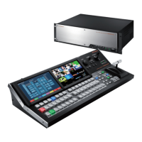
Connecting the V-1200HDR to the V-1200HD
To operate the V-1200HD remotely using a V-1200HDR unit, you connect the V-1200HDR and the V-1200HD using an Ethernet cable.
1. Connect the V-1200HDR and the V-1200HD using an Ethernet cable.
2. Turn on the power to the V-1200HD.
3. Turn on the power to the V-1200HDR.
4. The LINK indicator on the V-1200HDR and the LINK indicator on the V-1200HD light up, and a connection is established.
NOTE
5 Use a Category 5e or higher shielded Ethernet cable for connection. Crossover cables and straight cables are both supported.
5 Connect no devices other than the V-1200HD, V-1200HDR units, and computers installed with V-1200HD RCS to the same network.
5 Communication is not established if the V-1200HD and the V-1200HDR are connected after the power has been turned on. If the connection
has been made while in this state, communication can be established by resetting the power on just the V-1200HDR.
Connecting Multiple Controllers to the V-1200HD
Using an Ethernet switching hub, you can connect up to two controllers (V-1200HDR units or computers on which V-1200HD RCS is installed) to the
V-1200HD.
Connecting multiple controllers to the V-1200HD requires setting a dierent ID on each controller.
* When connecting two computer on which V-1200HD RCS is installed, in addition to the ID settings, the computers must also each be set to a
dierent IP address. For information on the value of the IP address to set, refer to “Making the Network Settings on the Computer” (p. 5).
1. Connect the V-1200HD and the two controllers to an Ethernet switching hub.
2. At the “ROOT MENU,” go to the CONTROL SURFACE section and tap <SETUP>.
* The screen is for V-1200HDR.
The CONTROL SURFACE SETUP screen appears.
3. At the ID section, tap the ID to set for the controller currently being operated.
4. For the other controller as well, carry out steps 2 and 3 to set the ID.
* Be sure to set the IDs to dierent values for each controller. Correct remote control becomes impossible if identical IDs are used.
5. The LINK indicator on all the controllers and the LINK indicator on the V-1200HD light up, and connections are established.
Requirements for the Switching Hub
The Ethernet switching hub used to connect controllers must satisfy the following conditions.
5 1000BASE-T-compatible switching hub recommended (IEEE 802.3ab, Gigabit Ethernet)
5 Must support 100BASE-TX interfaces (IEEE 802.3u, Fast Ethernet)
5 Must support full-duplex communication (simultaneous bidirectional communication)
Memo
5 Only one hub can be used. Cascade connection is not supported.
5 Carefully read the documentation for the switching hub used.
 Loading...