Reference Manual
00809-0100-4360, Rev BA
August 2008
2-25
Rosemount 1151
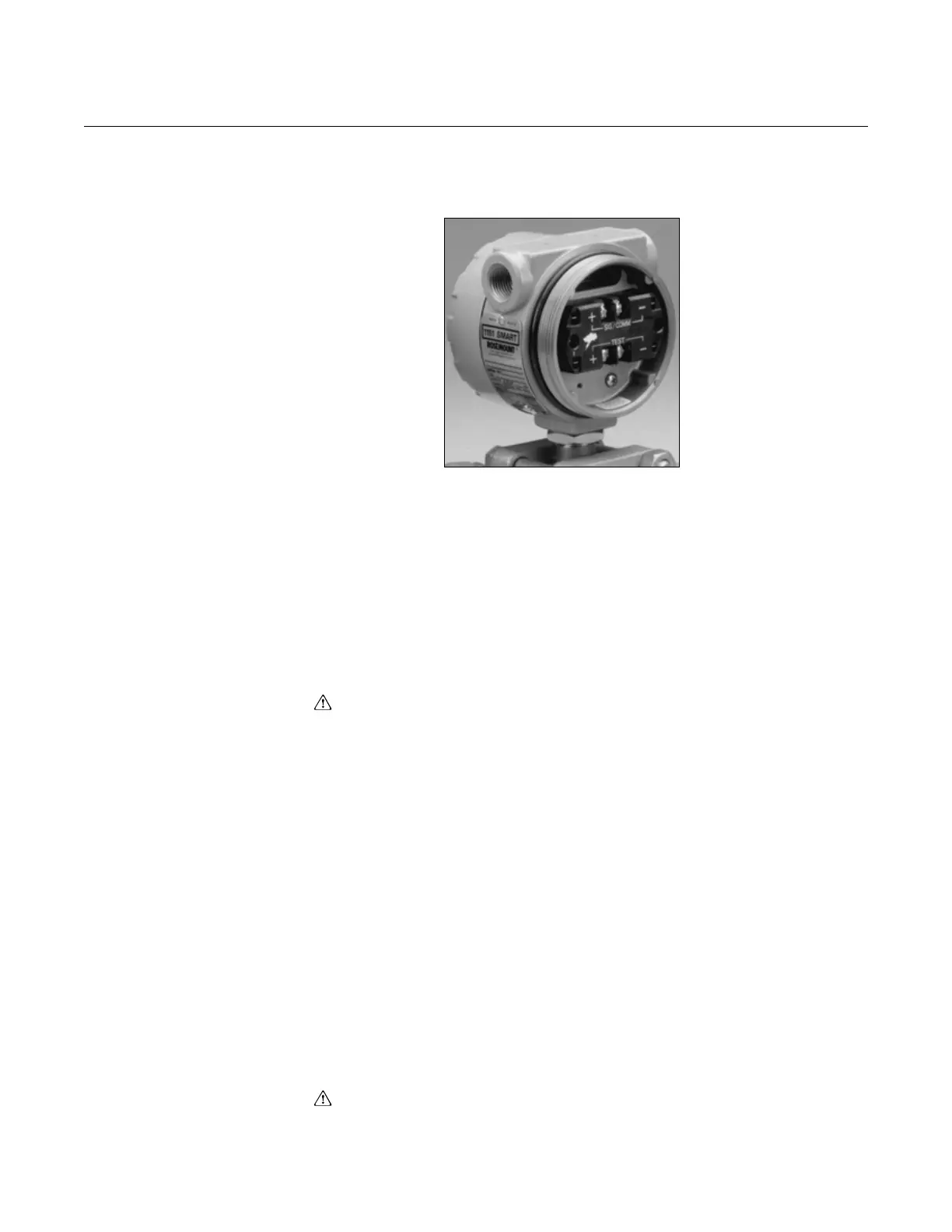
Figure 2-14. Transient
Protection and Filter Terminal
Block (Code R1).
Transient Protection and Filter Terminal Block (Option Code R1)
Option Code R1 provides EMI/RFI protection and the benefit of integral
transient protection. This terminal block can be ordered as a spare part to
retrofit existing Rosemount 1151 Transmitters with Option Code R2.
Terminal Block Installation
Use a Phillips screwdriver, a flat-blade screwdriver and the following steps to
install a retrofitable transient protection terminal block:
1. Turn off all power to the Rosemount 1151 on which the terminal block is
being installed.
2. Unscrew the transmitter terminal-side (indicated on the housing
nameplate) cover (on the high side of the transmitter) exposing the
standard terminal block.
3. Disconnect wiring to the terminal block.
4. Remove the single grounding screw and the two signal terminal screws,
with terminal eyelet washers, from the standard terminal block.
5. Set the retrofitable transient protection terminal block into the housing,
making sure the ground and signal terminals are properly aligned.
6. Insert the short mounting screws with washers in the mounting holes and
tighten the terminal block to the transmitter.
7. Turn the transient protector grounding sleeve, located in the grounding
hole, just enough to stabilize the unit on the transmitter. Overtightening
the grounding sleeve will shift the terminal block out of alignment.
8. Insert the long grounding screw with the square washer into the
grounding hole and tighten.
9. Connect the positive power supply wire to the transient protector terminal
screw labeled “+ SIGNAL”, and the negative power supply wire to the
terminal screw labeled “- SIGNAL.”
10. Attach the supplied label to the terminal side transmitter cover.
11. Replace the terminal side cover on the transmitter.