Reference Manual
00809-0100-4360, Rev BA
August 2008
Rosemount 1151
2-14
ELECTRICAL
CONSIDERATIONS
NOTE
Make sure all electrical installation is in accordance with national and local
code requirements.
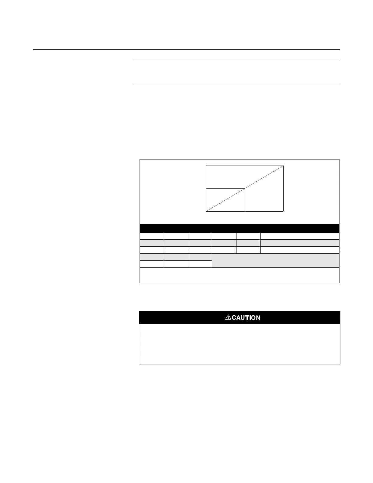
Power Supply The DC power supply should provide power with less than 2% ripple. The
total load is the sum of the resistance of the signal leads and the load
resistance of the controller, indicator, and related pieces. The resistance of
intrinsic safety barriers, if used, must be included. Figure 2-7 illustrates power
supply load limitations for the transmitter.
Figure 2-7. Power Supply Load
Limitations.
Conduit Installation
Recommended conduit connections are shown in Figure 2-8.
Code V
min
V
max
R
min
R
max
R
L
at Supply Voltage (V
s
)
S
(1)
(1) A minimum of 250 ohms is required for communication.
12 45 0 1650 R
L
= 43.5 (V
S
–12)
E
(2)
(2) For CSA Approvals (code E), V
max
= 42.4 V dc.
12 45 0 1650 R
L
= 50 (V
S
– 12)
G308501100 R
L
= 20 (V
S
– 30)
L 5 12 Low Power Minimum Load Impedance:
100 k
M814
R
max
R
L
R
min
V
min
V
S
V
max
Operating
Region
If all connections are not sealed, excess moisture accumulation can damage the
transmitter. Make sure to mount the transmitter with the electrical housing positioned
downward for drainage. To avoid moisture accumulation in the housing, install wiring
with a drip loop, and ensure the bottom of the drip loop is mounted lower than the
conduit connections or the transmitter housing.