Reference Manual
00809-0100-4360, Rev BA
August 2008
Rosemount 1151
5-16
Connecting the Electrical Housing to the Sensor
1. Insert the header assembly board through the electronics housing.
2. Use a sealing compound (Loctite
®
222 - Small Screw Threadlocker) on
the threads of the sensor module to ensure a watertight seal on the
housing.
3. Screw the sensor module into the electrical housing making sure that the
threads are fully engaged. Be careful not to damage or twist the sensor
leads.
4. Align the sensor module with the high and low pressure sides oriented
for convenient installation.
5. Tighten the lock nut.
Backup Ring and O-ring
Installation
All HP transmitters and GP Range 9 and 0 transmitters require metal backup
rings to ensure O-ring integrity. Figure 5-7 on page 5-16 illustrates the
position and orientation of the metal backup rings. (Backup rings are not
required on AP or DP transmitters or GP Range 3-8 transmitters.)
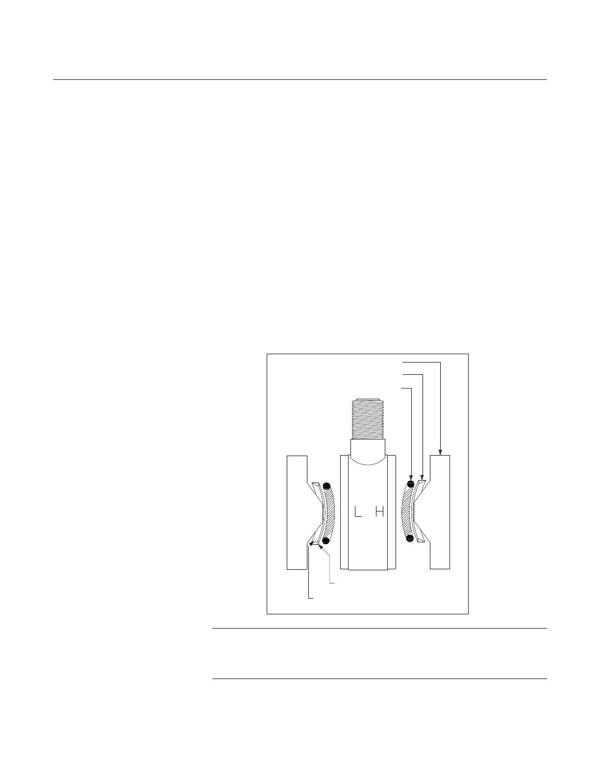
Figure 5-7. Detail Showing Process O-ring and Backup Ring Installation of Module Seal for Rosemount 1151HP
and GP Range 9 (GP Range 0 Requires Only One O-ring and Backup O-ring).
.
NOTE
Handle the backup ring carefully, as it is fragile. Examine the ring carefully.
One side is beveled, while the other side is flat. The flat side appears more
shiny when viewed from above.
Process Flange
Metal Back-up Ring
O-ring
Flat Side (shiny side)
Toward O-ring
Beveled Side Toward Process
Flange