Reference Manual
00809-0100-4360, Rev BA
August 2008
5-9
Rosemount 1151
Optional Plug-in Meters The optional indicating meters available for Rosemount 1151 transmitters are
listed in Section A: Reference Information. Please be aware of the following
information while assembling the meter assembly. Refer to Table A-11 on
page A-23 for part references.
• The display may be rotated in 90-degree increments
for convenient reading.
• If the display cover is removed for any reason, be sure the O-ring is in
place between the cover and housing before reattachment. To maintain
an explosion-proof condition, the glass in the meter cover should not be
disassembled for any reason.
Sensor Module Checkout The sensor module is not field repairable and must be replaced if found to be
defective. If no obvious defect is observed (such as a punctured isolating
diaphragm or fill fluid loss), the sensor module can be checked as follows.
1. Carefully pull the header assembly board off of the post connectors.
Rotate the board 180 degrees about the axis formed by the connecting
leads. The sensor module and electronics housing can remain attached
for checkout.
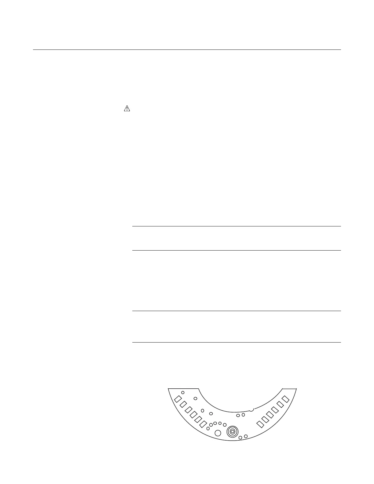
2. Check internal diode loops, forward and reverse bias: one loop is on pins
one and two, the other is on pins three and four. See Figure 5-3. Loop
resistance values should be nearly equal.
NOTE
Do not touch the transmitter housing when checking resistances, or a faulty
reading can result.
3. Check the resistance between the sensor module housing and pins one
through four. This checks the resistance between both capacitor plates
and the sensing diaphragm, which is grounded to the housing. This
resistance should be greater than 10 M
Ω.
4. Check the resistance between pin eight and the sensor module to ensure
that the module is grounded. Resistance should be zero.
NOTE
The above procedure does not completely test the sensor module. If circuit
board replacement does not correct the abnormal condition, and no other
problems are obvious, replace the sensor module.
Figure 5-3. Header Board
Connections.