Reference Manual
00809-0100-4360, Rev BA
August 2008
5-3
Rosemount 1151
SMART TROUBLESHOOTING
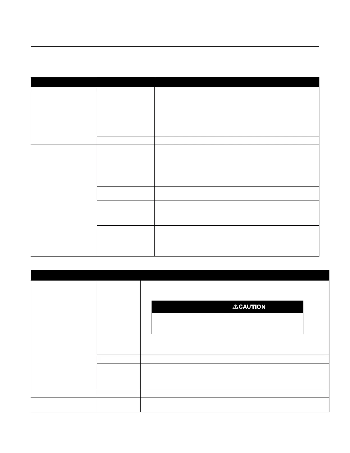
Table 5-1. Troubleshooting Symptoms and Corrective Action.
Symptom Potential Source Corrective Action
Transmitter does not
communicate with the HART
Communicator
Loop Wiring Check for a minimum of 250 Ω resistance between the power supply and the
communicator connection.
Check for adequate voltage to the transmitter. (If the communicator is
connected and 250
resistance is properly in the loop, then the loop requires
a minimum of 17 volts to operate.)
Check for intermittent shorts, open circuits, and multiple grounds.
Specify the transmitter by tag number. See the display sequence below.
I.S. Barrier Refer to appropriate I.S. Barrier documentation.
High Output Primary Element
Impulse Piping
Check for restrictions at primary element.
Check for leaks or blockage.
Ensure that blocking valves are fully open.
Check for entrapped gas in liquid lines and for liquid in dry lines.
Ensure that the density of fluid in impulse lines is unchanged.
Check for sediment in transmitter process flanges.
Power Supply Check the power supply output voltage at the transmitter. It should be 12 to 45
V dc.
Transmitter Electronics Connect the HART Communicator and enter the XMTR TEST mode to
determine any electronic failures.
Make sure that post connectors are clean.
If the electronics are still suspect, substitute new electronics.
Sensing Element The sensing element is not field repairable and must be replaced if found to be
defective. See “Disassembly procedure” later in this section for instructions on
disassembly. Check for obvious defects, such as a punctured isolating
diaphragm or fill fluid loss, and contact your local Emerson Process
Management representative.
Symptom Potential Source Corrective Action
Erratic Output Loop Wiring Check for adequate voltage to the transmitter. It should be 12 to 45 V dc with no load.
Check for intermittent shorts, open circuits and multiple grounds.
Connect the HART Communicator and enter the LOOP TEST mode to generate signals
of 4 mA, 20 mA, and user-selected values.
Process Pulsation Adjust the electronic damping with the HART Communicator.
Transmitter
Electronics
Connect the communicator and perform a transmitter test to
determine any electronic failures.
Make sure the post connectors are clean.
If the electronics are still suspect, substitute new electronics.
Impulse Piping Check for entrapped gas in liquid lines and for liquid in dry lines.
Low Output or No Output Primary Element Check the insulation and condition of primary element.
Note any changes in process fluid properties that may affect output.
Do not use over 45 volts to check the loop, or damage to the
transmitter electronics may result.