Reference Manual
00809-0100-4360, Rev BA
August 2008
Rosemount 1151
5-4
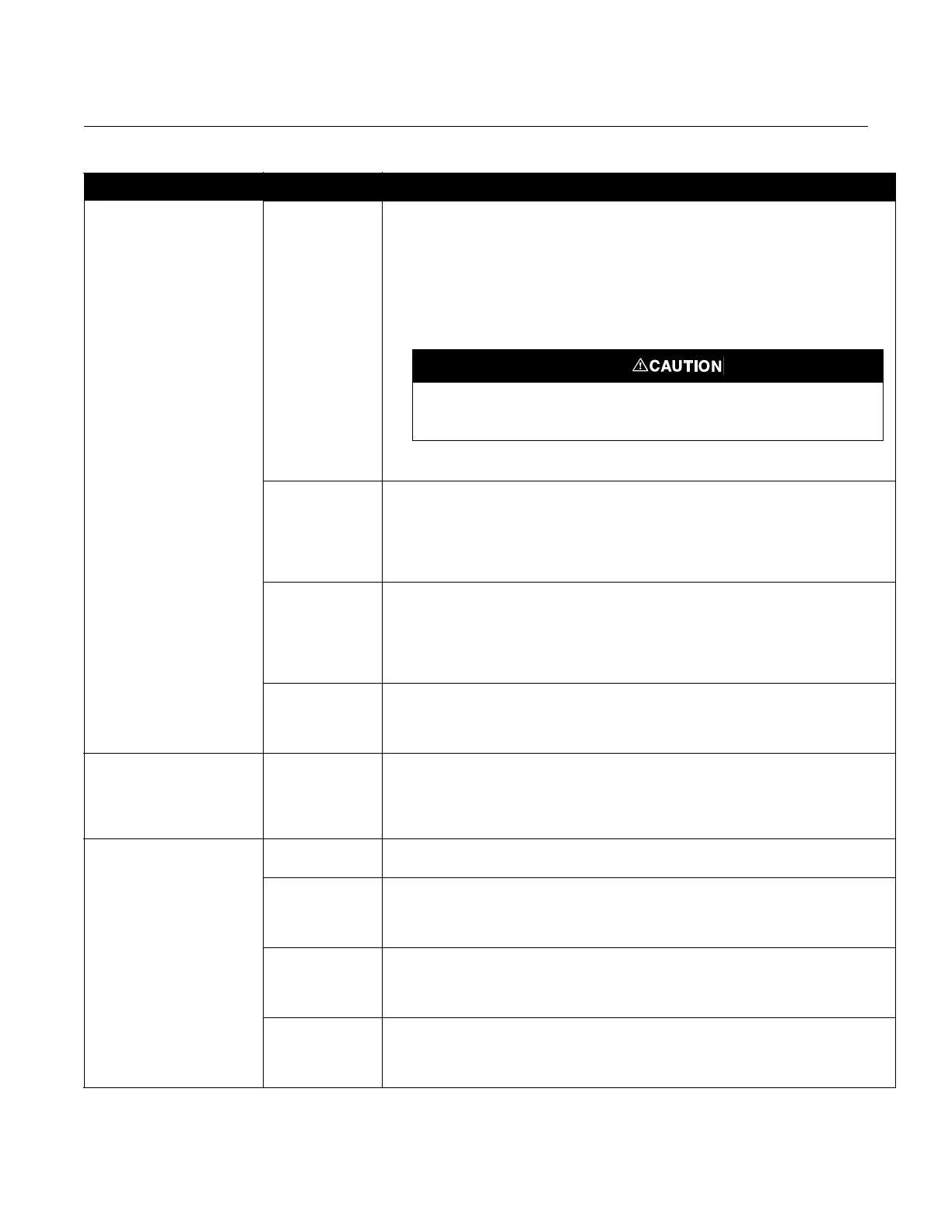
Loop Wiring Check for adequate voltage to the transmitter. It should be 12 to 45 V dc.
Check the milliamp rating of the power supply against the total current being drawn for all
transmitters being powered.
Check for shorts and multiple grounds.
Check for proper polarity at the signal terminal.
Check loop impedance.
Check whether the transmitter is in multidrop mode, thus locking the output at 4 mA.
Connect the communicator and perform a loop test.
Check wire insulation to detect possible shorts to ground.
Impulse Piping Ensure that the pressure connection is correct.
Check for leaks or blockage.
Check for entrapped gas in liquid lines.
Check for sediment in the transmitter process flange.
Ensure that blocking valves are fully open and that bypass valves are tightly closed.
Ensure that density of the fluid in the impulse piping is unchanged.
Transmitter
Electronics
Connect the communicator and check the sensor limits to ensure
calibration adjustments are within the sensor range.
Connect the communicator and perform a transmitter test to
determine electronics failure.
Make sure the post connectors are clean.
If the electronics are still suspect, substitute new electronics.
Sensing Element The sensing element is not field repairable and must be replaced if found to be defective.
See “Disassembly procedure” later in this section for instructions on disassembly. Check
for obvious defects, such as punctured isolating diaphragm or fill fluid loss, and contact
your local Emerson Process Management representative.
Transmitter Does Not
Characterize Properly
Pressure
Source/Correction
Check for restrictions or leaks.
Check for proper leveling or zeroing of the pressure source.
Check weights/gauge to ensure proper pressure setting.
Determine if the pressure source has sufficient accuracy. (The pressure source
should be at least three times more accurate that the Rosemount 1151 Smart.)
Transmitter Does Not
Characterize Properly
mA Meter Determine if the mA meter is functioning properly.
Power Supply Check the power supply output voltage at transmitter.
It should be 12 to 45 V dc with no load.
Check for a minimum of 250 Ω resistance between the HART Communicator
and the power supply.
Transmitter
Electronics
Connect the communicator and perform a transmitter test to determine
any electronic failures.
Make sure the post connectors are clean.
If electronics are still suspect, substitute with new electronics.
Sensing Element The sensing element is not field repairable and must be replaced if found to be defective.
See “Disassembly procedure” later in this section for instructions on disassembly. Check
for obvious defects, such as punctured isolating diaphragm or fill fluid loss, and contact
your local Emerson Process Management representative.
Symptom Potential Source Corrective Action
Do not use over 45 volts to check the loop, or damage to the transmitter electronics
may result.