Reference Manual
00809-0100-4360, Rev BA
August 2008
5-15
Rosemount 1151
1. Carefully pull the header assembly board off of the post connectors.
Rotate the board 180 degrees about the axis formed by the connecting
leads. The sensor module and electronics housing can remain attached
for checkout.
NOTE
Do not touch the transmitter housing when checking resistances, or a faulty
reading can result.
2. Check the resistance between the sensor module housing and pins one
through four. This checks the resistance between both capacitor plates
and the sensing diaphragm, which is grounded to the housing. This
resistance should be greater than 10 M.
3. Check the resistance between pin eight and the sensor module to ensure
that the module is grounded. Resistance should be zero.
NOTE
The above procedure does not completely test the sensor module. If circuit
board replacement does not correct the abnormal condition, and no other
problems are obvious, replace the sensor module.
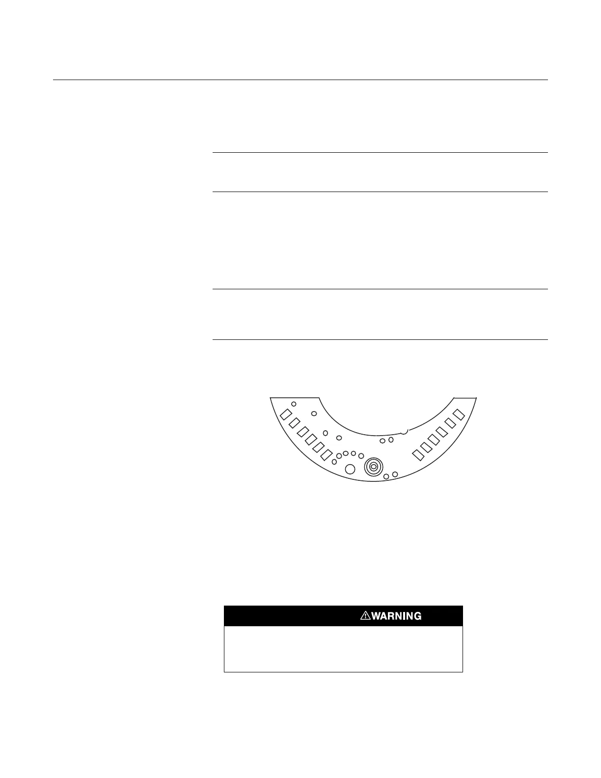
Figure 5-6. Header Board
Connections.
.
Reassembly Procedure Follow these procedures carefully to ensure proper reassembly.
Preliminary Precaution
Inspect all O-rings and replace if necessary. Lightly grease with silicone oil to
ensure a good seal. Use halocarbon grease for inert fill options.
Explosions can cause death or serious injury. Both
transmitter covers must be fully engaged to meet
explosion-proof requirements.