Reference Manual
00809-0100-4360, Rev BA
August 2008
Rosemount 1151
6-12
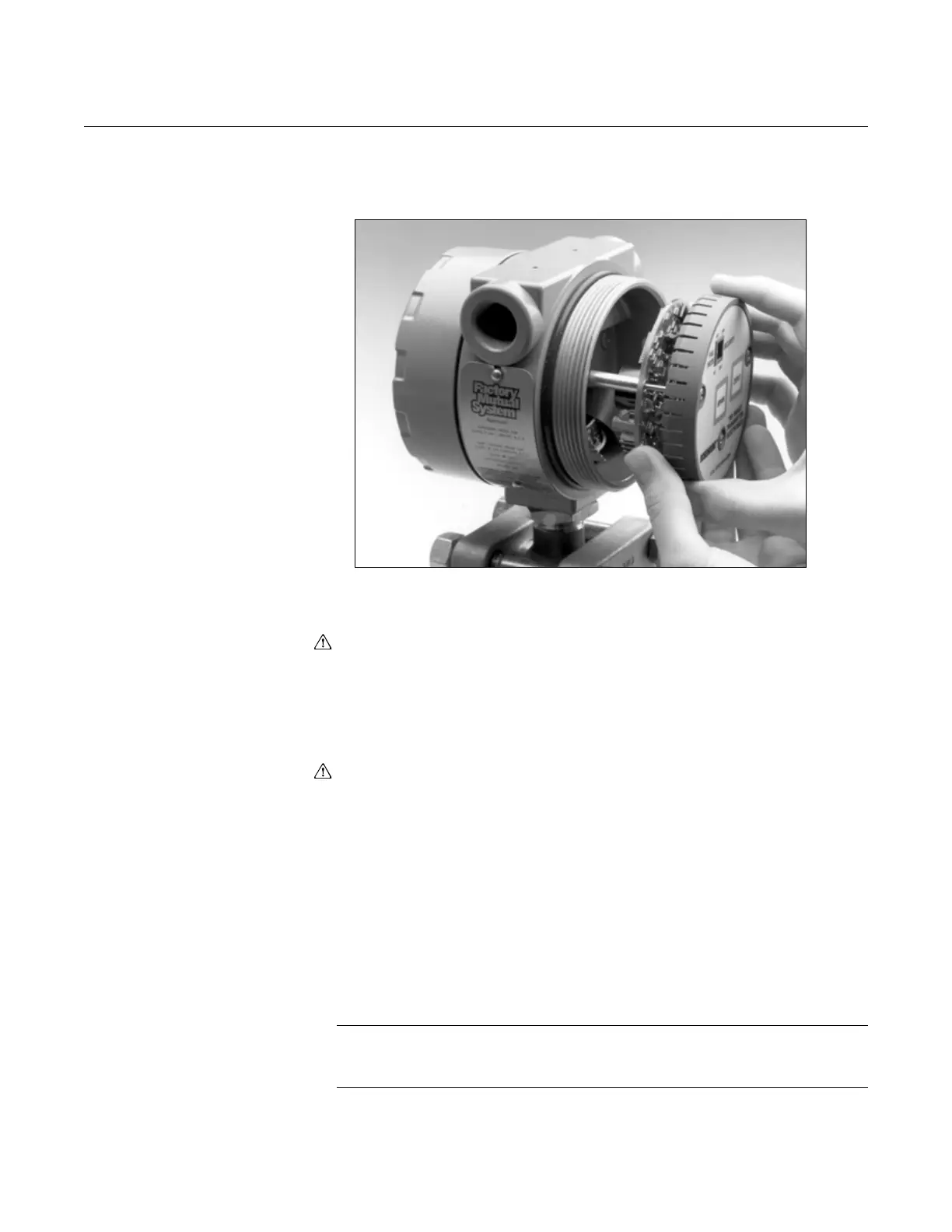
4. Align the smart electronics assembly with the bayonet connector pins,
making sure all pins line up with the proper receptacles. Next, push the
assembly slowly inward until it is fully seated.
5. Tighten the three captive screws on the smart electronics assembly to
secure it in place.
6. Attach the electronics cover provided in the smart retrofit kit, and tighten
securely.
7. Remove the cover from the terminal side of the transmitter.
Two eyelets that fit under the + and – signal terminal screws are provided to
facilitate connections to HART-based communicator. The signal terminal is
the upper block as indicated on the transmitter housing.
8. Remove the signal terminal + and – screws. Attach an eyelet to each
screw, and reinsert the screws.
9. Reattach the cover on the terminal side, and tighten securely.
CHARACTERIZATION The transmitter is now ready to be characterized. Characterization is a
one-time calibration of the sensor in the Rosemount 1151 Transmitter. During
characterization, known pressures are applied to the sensor, and
corresponding digital values are stored in the EEPROM located in the smart
transmitter electronics. The microprocessor uses these values to make
linearization corrections. The digital-to-analog converter then converts the
corrected digital signal into a 4–20 mA dc output. The Rosemount 1151
Transmitter will stay in high alarm (approximately 22 mA output) until the
characterization sequence is completed.
NOTE
The transmitter must be re-characterized if either the sensor module or the
smart transmitter electronics are repaired or replaced.