Reference Manual
00809-0100-4360, Rev BA
August 2008
2-15
Rosemount 1151
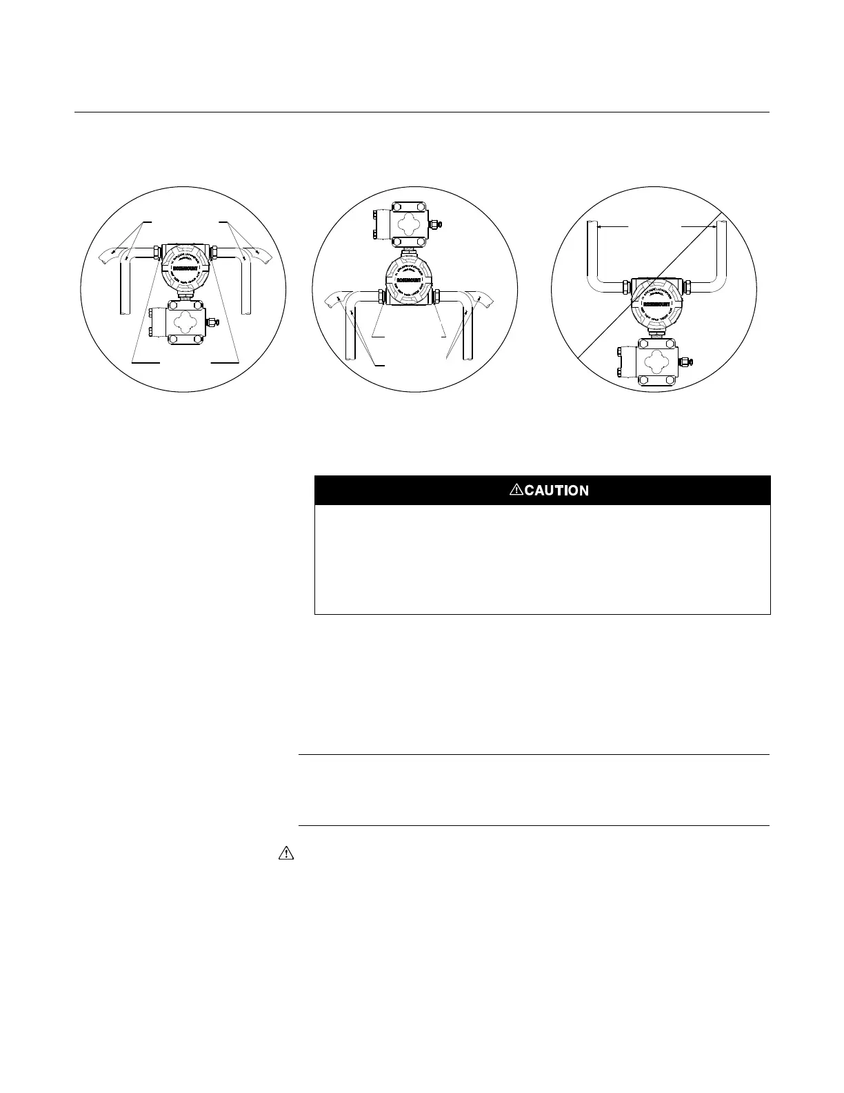
Figure 2-8. Conduit Installation
Diagrams.
Wiring
The signal terminals and test terminals are located in a compartment of the
electronics housing that is separate from the transmitter electronics. The
nameplate on the side of the transmitter indicates the locations of both of
these compartments. The upper pair of terminals are the signal terminals and
the lower pair are the test terminals. The test terminals have the same 4–20
mA output as the signal terminals and are only for use with the optional
integral meter or for testing.
NOTE
An alternate location to connect an ammeter is on the set of terminals labeled
“TEST.” Connect the positive lead of the ammeter to the positive test terminal,
and the negative lead of the ammeter to the negative test terminal.
To make connections, remove the cover on the side marked “Terminal” on the
nameplate. All power to the transmitter is supplied over the signal wiring.
Connect the lead that originates at the positive side of the power supply to the
terminal marked “+” and the lead that originates at the negative side of the
power supply to the terminal marked “–”. No additional wiring is required.
Do not run signal wiring in conduit or open trays with power wiring or near
heavy electrical equipment.
For improved performance against EMI/RFI effects, refer to “Terminal Blocks”
on page 2-24 for information on transient protection terminal blocks.
Sealing
Compound
Conduit
Lines
CORRECT CORRECT INCORRECT
Possible
Conduit Line
Positions
Sealing
Compound
Possible
Conduit Line
Positions
Do not connect the power signal wiring to the test terminals. Voltage may burn out the
reverse-polarity protection diode in the test connection. If the test diode is destroyed,
then the transmitter can still be operated without local indication by jumping the test
terminals.
High voltage (greater than 50 V and greater than 0.005 amperes) can cause
damage to the transmitter. Do not apply high voltage to the test terminals.