Reference Manual
00809-0100-4360, Rev BA
August 2008
Rosemount 1151
5-8
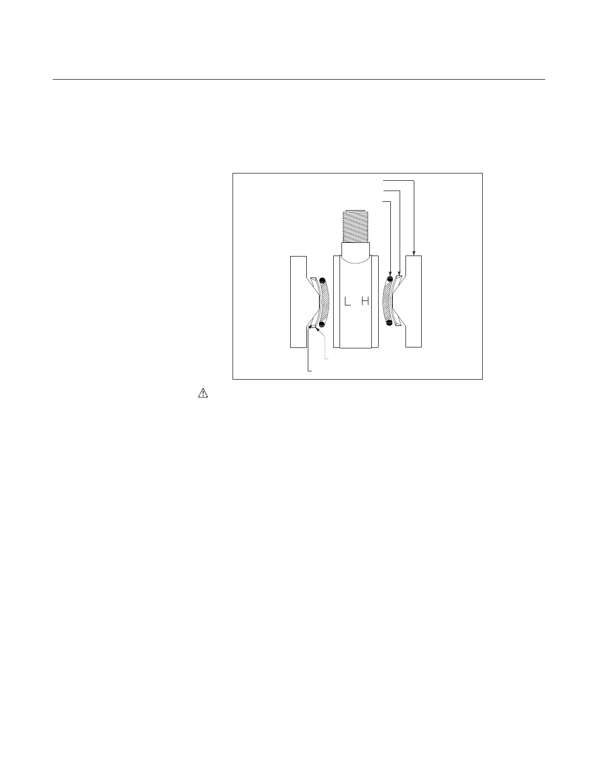
Figure 5-2. Detail Showing
Process O-ring and Backup
Ring Installation of Module Seal
for Rosemount 1151HP and GP
Range 9 (GP Range 10
Requires Only One O-ring and
Backup O-ring).
4. For all HP transmitters and GP transmitters Ranges 9 and 10, place the
backup ring, shiny side down, on top of the O-ring. This places the flat
side of the backup ring against the O-ring.
5. Carefully place the flange on top of the module, beveled side down so
that the beveled flange surface mates with the beveled surface of the
backup ring.
6. Keeping the flange and module together, turn them over so the “L” side is
up. Repeat Steps 3 through 5. As before, the flat side of the backup ring
must rest against the O-ring.
7. Insert the four flange bolts.
8. Tighten the nuts finger tight, making sure the flanges remain parallel. The
transmitter may now be moved without disturbing the O-rings.
a. Tighten one bolt until the flanges seat.
b. Torque down the bolt diagonally across.
c. Torque down the first bolt.
d. Torque down the two remaining bolts.
e. Inspect the flange-to-sensor seating to be sure that the flanges are
not cocked.
f. Check that all four bolts are tightened to approximately 33 ft.-lb (39
Nm).
9. Recalibrate the transmitter.
Process Flange
Metal Back-up Ring
O-ring
Flat Side (shiny side) Toward O-ring
Beveled Side Toward Process Flange