53
Reference Manual
00809-0100-4809, Rev DA
Section 2: Installation
September 2015
Installation
b. As the orange stripes approach the support plate, remove the power drill and continue
cranking manually. Place a finger above the packing gland while cranking. When
movement stops, the sensor is in contact with the opposite side wall.
c. Turn the handle an additional
1
/4 to
1
/2 turn to secure the sensor.
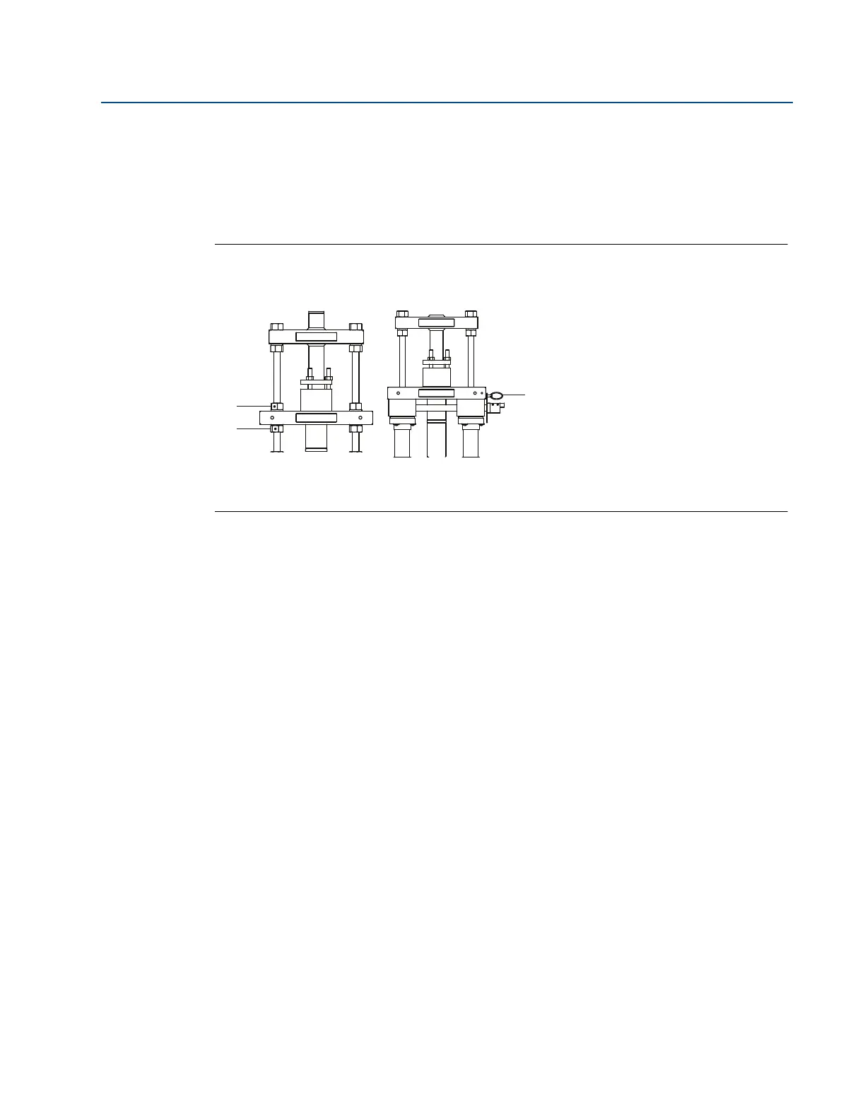
3. Secure the drive by inserting the drive lock pin as shown in Figure 2-36.
Figure 2-36. Insert Annubar Sensor
Step 8: Retract the Annubar sensor
Manual Drive (M)
1. Retract by rotating the drive nuts counter-clockwise. The nuts must be turned
alternately, about two turns at a time, to prevent binding caused by unequal loading.
2. Continue this procedure until the rod end nuts are against the packing body
mechanism.
Gear Drive (G)
1. Remove the drive lock pin.
2. Retract the sensor by rotating the crank counter-clockwise. If a power drill with an
adapter is used, do not exceed 200 rpm.
3. Retract until the rod end nuts are against the packing body mechanism.
Manual drive (M) Gear drive (G)
A. Lock nuts
B. Drive nuts
C. Drive lock pin
C
 Loading...


