Reference Manual
00809-0100-4664, Rev BA
January 2010
E-39
Rosemount 8712
GENERIC MANUFACTURER SENSORS
Generic Manufacturer
Sensor to
Rosemount 8712
Transmitter
Identify the Terminals First check the sensor manufacturer’s manual to identify the appropriate
terminals. Otherwise, perform the following procedure.
Identify coil and electrode terminals
1. Select a terminal and touch an ohmmeter probe to it.
2. Touch the second probe to each of the other terminals and record the
results for each terminal.
3. Repeat the process and record the results for every terminal.
Coil terminals will have a resistance of approximately 3-300 ohms.
Electrode terminals will have an open circuit, if the sensor is empty. With a full
sensor, the electrode terminals will have a resistance of approximately 1000
ohms.
Identify a chassis ground
1. Touch one probe of an ohmmeter to the sensor chassis.
2. Touch the other probe to the each sensor terminal and the record the
results for each terminal.
The chassis ground will have a resistance value of one ohm or less.
Wiring Connections Connect the electrode terminals to Rosemount 8712 terminals
18 and 19. The electrode shield should be connected to terminal 17.
Connect the coil terminals to Rosemount 8712 terminals 1, 2, and
.
If the Rosemount 8712 Transmitter indicates a reverse flow condition, switch
the electrode wires connected to terminals 8 and 19.
Generic Sensor Rosemount 8712E/8732E
Coil Circuit Connections
Coil Positive 1
Coil Negative 2
Case Ground
Electrode Circuit Connections
Electrode Positive 18
Electrode Negative 19
Case Ground 17
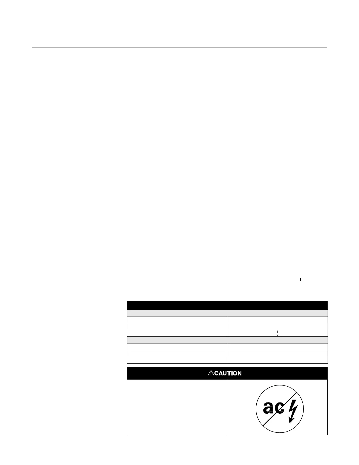
This is a pulsed DC magnetic flowmeter.
Do not connect AC power to the sensor
or to terminals 1 and 2 of the
transmitter, or replacement of the
electronics board will be necessary.