Reference Manual
00809-0100-4664, Rev BA
January 2010
Rosemount 8712
2-10
Internal
The 4–20 mA analog power loop may be powered from the transmitter
itself. Resistance in the loop must be 1,000 ohms or less. If a Handheld
Communicator or control system will be used, it must be connected across
a minimum of 250 ohms resistance in the loop.
External
HART multidrop installations require a 10–30 V DC external power source
(see Multidrop Communications on page 3-16). If a Handheld
Communicator or control system is to be used, it must be connected
across a minimum of 250 ohms resistance in the loop.
To connect external power to the 4–20 mA loop, complete the
following steps.
1. Ensure that the power source and connecting cable meet the
requirements outlined above and in Electrical Considerations on page
2-7.
2. Turn off the transmitter and analog power sources.
3. Run the power cable into the transmitter.
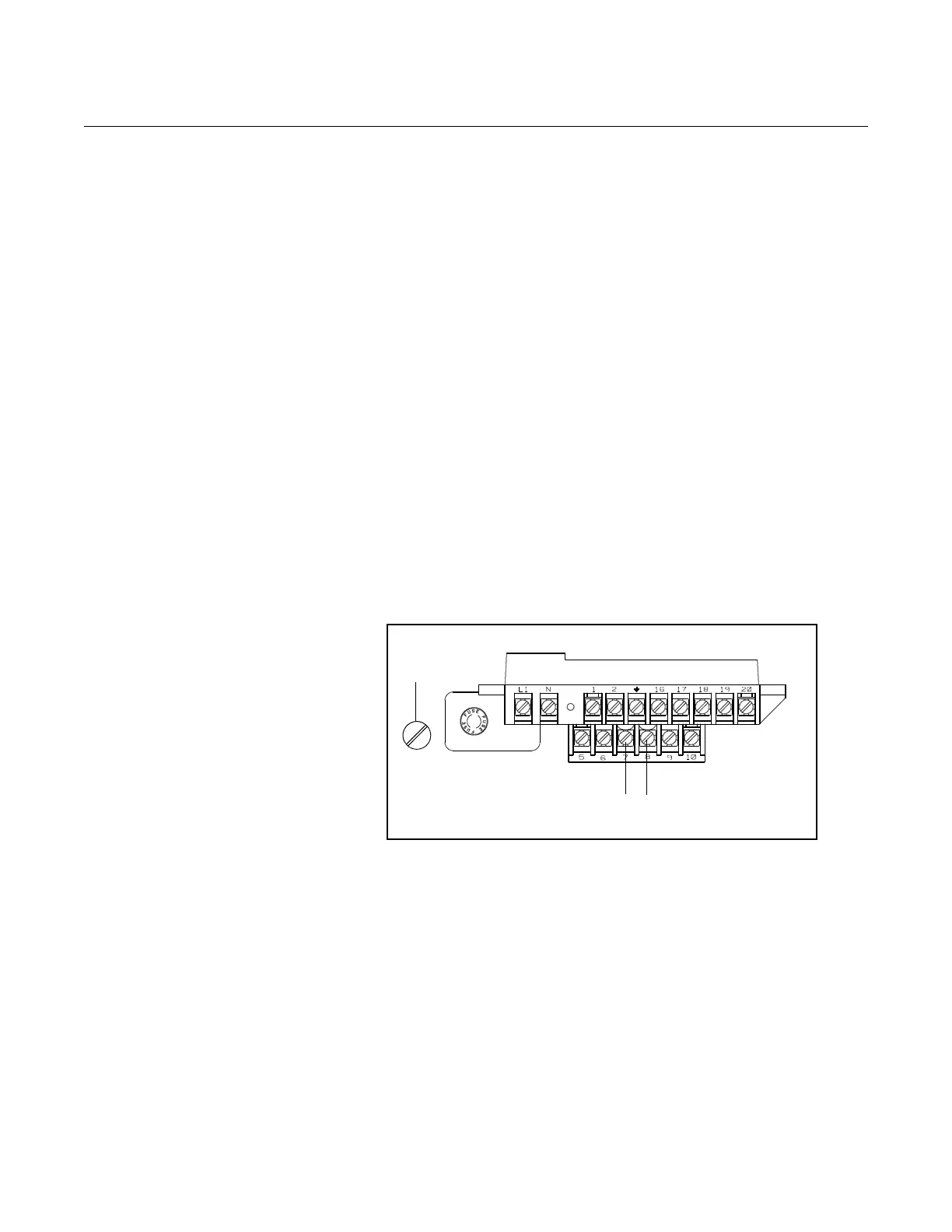
4. Connect –DC to Terminal 8.
5. Connect +DC to Terminal 7.
Refer to Figure 2-6 on page 2-10.
Figure 2-6. 4–20 mA Loop
Power Connections
Connect Pulse Output
Power Source
The pulse output function provides an isolated switch-closure frequency
signal that is proportional to the flow through the sensor. The signal is typically
used in conjunction with an external totalizer or control system. The following
requirements apply:
–4–20 mA power
+4–20 mA power
Fuse
Supply Voltage: 5 to 24 V DC
Load Resistance: 1,000 to 100 k ohms (typical
5 k)
Pulse Duration: 1.5 to 500 msec (adjustable), 50% duty cycle below 1.5 msec
Maximum Power: 2.0 watts up to 4,000 Hz and 0.1 watts at 10,000 Hz
Switch Closure: solid state switch