Reference Manual
00809-0100-4664, Rev BA
January 2010
E-21
Rosemount 8712
Fischer and Porter
Generic Sensor to
Rosemount 8712
Transmitter
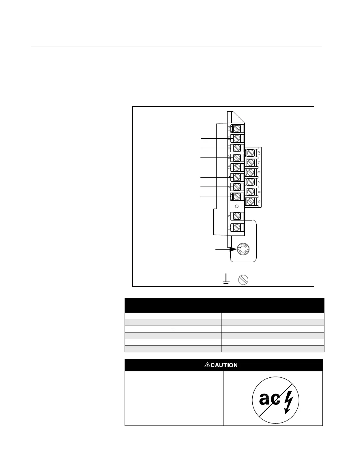
Connect coil drive and electrode cables as shown in Figure E-19.
Figure E-19. Generic Wiring
Diagram for Fischer and Porter
Sensors and Rosemount 8712
Table E-17. Fischer and Porter Generic Sensor Wiring Connections
Rosemount 8712
Fischer and Porter
Generic Sensors
1M1
2 M2
Chassis Ground
17 3
18 1
19 2
Electrodes
2
Coils
Chassis
ROSEMOUNT 8712
TRANSMITTER
FISCHER AND PORTER
SENSORS
Fuse
1
3
M2
M1
This is a pulsed DC magnetic flowmeter.
Do not connect AC power to the sensor
or to terminals 1 and 2 of the
transmitter, or replacement of the
electronics board will be necessary.