Reference Manual
00809-0100-4664, Rev BA
January 2010
Rosemount 8712
2-12
When configured as an output, the following requirements apply:
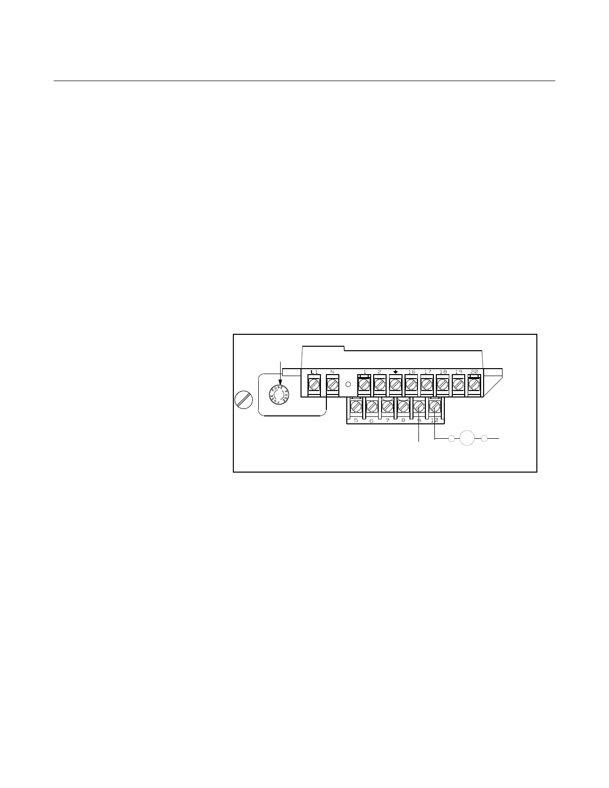
When using channel 1 as a digital output, the power source must be
connected to the transmitter. See Figure 2-10 for more details on this
connection.
When connecting power to channel 1, complete the following steps:
1. Ensure that the power source and connecting cable meet the
requirements outlined previously.
2. Turn off the transmitter and auxiliary power sources.
3. Run the power cable to the transmitter.
4. Connect –DC to terminal 10.
5. Connect +DC to terminal 9.
Figure 2-9. Connect Digital Input
1 to Relay or Input to Control
System
Connect Auxiliary
Channel 2
Auxiliary channel 2 is configured to provide a digital output based on the
configuration parameters set in the transmitter.
The following requirements apply to this channel:
When connecting power to channel 2, complete the following steps:
1. Ensure that the power source and connecting cable meet the
requirements outlined previously.
2. Turn off the transmitter and auxiliary power sources.
3. Run the power cable to the transmitter.
4. Connect –DC to terminal 20.
5. Connect +DC to terminal 16.
See Figure 2-10 for more details on this connection.
Supply Voltage: 5 to 28V DC
Maximum Power: 2 watts
Switch Closure: optically isolated solid state switch
DC–
DC+
Fuse
Control Relay
or Input
Supply Voltage: 5 to 28V DC
Maximum Power: 2 watts
Switch Closure: optically isolated solid state switch