Reference Manual
00809-0100-4664, Rev BA
January 2010
Rosemount 8712
5-16
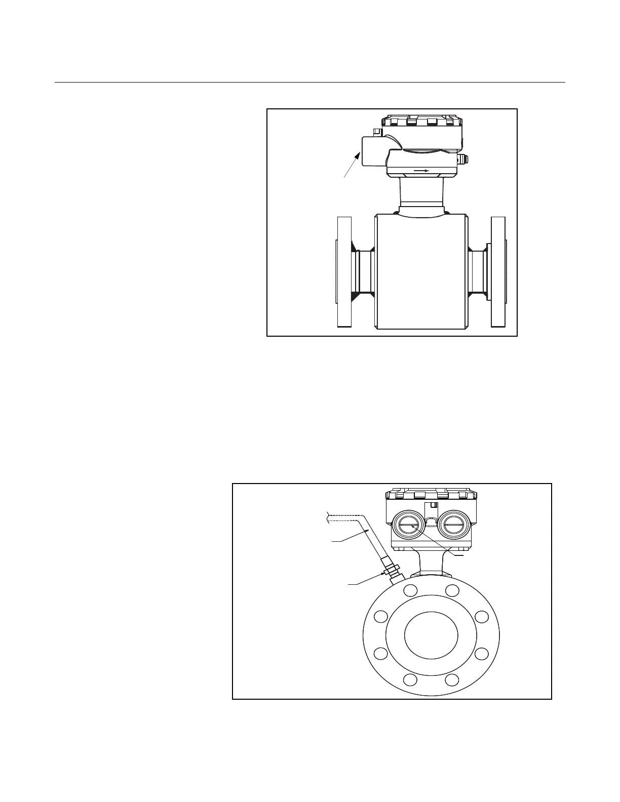
Figure 5-17. Standard Housing
Configuration — Sealed Welded
Housing (Option Code W0)
Relief Valves The first optional configuration, identified by the W1 in the model number
option code, uses a completely welded coil housing. This configuration does
not provide separate electrode compartments with external electrode access.
This optional housing configuration provides a relief valve in the housing to
prevent possible overpressuring caused by damage to the lining or other
situations that might allow process pressure to enter the housing. The relief
valve will vent when the pressure inside the sensor housing exceeds 5 psi.
Additional piping (provided by the user) may be connected to this relief valve
to drain any process leakage to safe containment (see Figure 5-18).
Figure 5-18. Coil-Housing
Configuration — Standard
Welded Housing With Relief
Valve (Option Code W1)
1
/2–14 NPT Conduit
Connection
(no relief valve)
Optional:
Use drain port to
plumb to a safe area
(Supplied by user)
1
/2 – 14 NPT Conduit
Connection
¼'' NPT – 5 psi
Pressure Relief Valve