Reference Manual
00809-0100-4664, Rev BA
January 2010
2-13
Rosemount 8712
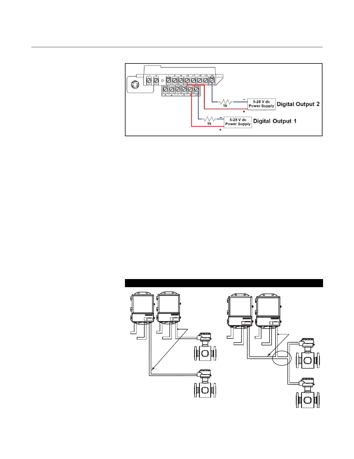
Figure 2-10. Connecting Digital
Outputs
SENSOR CONNECTIONS This section covers the steps required to physically install the transmitter
including wiring and calibration.
Rosemount Sensors To connect the transmitter to a non-Rosemount sensor, refer to the
appropriate wiring diagram in Appendix D: Wiring Diagrams. The calibration
procedure listed is not required for use with Rosemount sensors.
Transmitter to
Sensor Wiring
Flanged and wafer sensors have two conduit ports as shown in Figures 4-13,
4-14, 4-15, and 4-16. Either one may be used for both the coil drive and
electrode cables. Use the stainless steel plug that is provided to seal the
unused conduit port.
A single dedicated conduit run for the coil drive and electrode cables is
needed between a sensor and a remote transmitter. Bundled cables in a
single conduit are likely to create interference and noise problems in your
system. Use one set of cables per conduit run. See Figure 2-11 for proper
conduit installation diagram and Table 2-3 for recommended cable. For
integral and remote wiring diagrams refer to Figure 2-13.
Figure 2-11. Conduit Preparation
Correct Incorrect
Coil Drive
and
Electrode
Cables
Power
Power
Outputs
Outputs
Coil Drive
and
Electrode
Cables
Power
Outputs
Power
Outputs